Ladies and Gentlemen...
Land mine are explosive devices concealed under or camouflaged on the ground, and designed to destroy or disable enemy targets, ranging from personel to vehicles and tanks, as they pass over or near them. These devices were widely used in WWII and their deactivation was always a huge problem. The vehicle we are going to see today was one of the attempts to manufacture a self-propelled device that could "clear" minefields quickly and safely. meet the Matilda Scorpion I flail tank, one of the really effective pioneers who were employed in this task.
 |
| Kojak would like to collect the mines, but this task is too dangerous... |
 |
| Matilda Scorpion I flail tank under field maintenance The deflector shield of the rotor operator is in rectangular shape North African desert - 2 November 1942. font:IWM E 18868 |
History:
The Matilda Scorpion I was a specialized vehicle, built to be a minefield destroyer, developed in the Middle East and used in North Africa.
 |
| Matilda Scorpion II flail tank in the Second Battle of El Alamein Western Desert - Egypt 5 November -1942 font: IWM E19019 |
Other contemporary Matilda tanks that were employed in this task were the Valentine Scorpion and the Grant Scorpion.
 |
| Valentine Scorpion flail tank font: IWM MH 9308 |
 |
| General Grant Scorpion flail tank in a Sicilian street, 1943. |
Development of the concept:
The idea of the mine flail tank began in 1941 with Abraham S. J. du Toit,, an automotive engineer in civilian life and a sergeant in the South African Artillery. Toit developed a device that detonated mines by hitting the ground with heavy chains or steel cables, driven by a rotating drum. A test apparatus was built into a truck and given a practical demonstration in Pretoria, South Africa, where a short film was produced and sent to General Claude Auchinleck.
 |
| General Claude John Eyre Auchinleck Commander-in-chief of the Middle East Theatre July - 1941. |
After General Auchinleck saw the film, he thought the idea was brilliant and sent Sergeant du Toit to England to develop his idea and build a more robust prototype mounted on a tank chassis for use in combat. Sergeant du Toit was soon promoted to Major and was closely involved in the development of what would become the Matilda Baron in Britain.
This used flails, mounted on a rotor at the end of 3 meters long arms, to whip the ground and detonate mines. These arms could be raised or lowered by means of linkages and hydraulic pistons.
By the end of 1942 the Baron was ready for production. This used two Bedford engines to power the device, and had a specially built operator's cabin in place of the normal turret.
 |
| Matilda Baron flail tank left view font: IWM MH 3681 |
 |
| Matilda Baron flail tank right view font: IWM MH 3682 |
 |
| Matilda Baron flail tank in action The mess was big, but the equipment proved to be effective. font: IWM H 31847 |
Although the Matilda Baron never saw real combat, it provided the knowledge and experience that eventually led to the development of the operational General Hobart's famous Sherman "Crab" flail tank (which mechanically was very similar), of important use in the Normandy landings, in June, 1944 and after.
 |
| Sherman V Crab flail tank during the advance towards Venraij, Holland. 17 October 1944 font:IWM BU 1213 |
Matilda Scorpion:
Before Sergeant du Toit left for England, he shared his idea with Captain Norman Berry, South African Chief Mechanical Engineer, 8th Army. Captain Berry was impatiently waiting for the results (through bureaucracy) from England and, on his own initiative, decided to do some experiments with the idea of his own, while the 8th Army was still entrenched along the Gazala Line, in the spring of 1942.
Incredibly, the idea spontaneously arose in another sector, few months later, during the summer. Lieutenant Colonel Mill Colman, a member of the South African Engineer Corps, developed what he saw as a new idea for mine clearance: Inspiration struck when he noticed a tracked vehicle passing by with a bunch of barbed wire tangled in the track sprockets. With each revolution of the sprocket, the barbed wire whipped the ground with great force. Based on this, he thought it might be possible to build a flail device that could detonate mines.
Major L. A. Girling, Commander of the 21st South African Corps Field Park Company, was tasked with building the first experimental unit. They called it a "mine destruction device". Captain Berry, hearing of this "revival" of the flail idea, told Major Girling about similar earlier developments and described how Sergeant du Toit had been sent to England by General Claude Auchinleck to work on a similar idea, under conditions of strict secrecy.
So secret, in fact, that Allied Command in the Middle East had forgotten all about it. Captain Berry enthusiastically dug up the reports of his earlier experiment and handed the idea for the contraption to Major Girling's team of engineers, consisting of himself, Captain G.J. Barry, Lieutenant Hofmann and Lieutenant C.D.B. Cramb. Work on the flail prototype began immediately and on August 6, 1942, the first mock-up was completed.
This first prototype of the flail was named the Durban Mark I, after Lieutenant Colonel Colman's hometown in South Africa. The Durban Mark I (later, Matilda Scorpion) incorporated many of Captain Berry's ideas, including an auxiliary Ford V8 engine, mounted in a sponson (an armored box) on the right side of the roller struts in the hull of a Matilda II tank, in a flush box, and then in the drum suspended above the ground. In this armored box, the operator could control the rotor and restart the engine.
The horizontal flail rotor was supported by two simple lattice beam arms, fixed and non-articulated, as were those of the Matilda Baron. The left arm (the non-motorized one) could be rectangular or triangular. The rectangular version it featured four vertical trusses on the frontal part of the left and right arms, while the triangular left-arm version had two vertical trusses on the right arm and only one on the left arm.
 |
| Matilda Scorpion I with rectangular left arm (red arrow) - left view and four vertical lattices on the frontal part of the left arm (green arrows) |
 |
| A "triangular" Matilda Scorpion II being transported by a Diamond T980 tank transporter. (right view.) Notice the two vertical lattices in right arm (red) no visible air filter in the top of the engine box (green) and the triangular deflector shield for the rotor operator (blue). 27 January 1943. font: modified from IWM E 21707 |
In the pics, we can already observe many construction differences between individual Scorpions: the shape of the left arm, the shape of the armored box where the operator controlled the engine, the presence or absence of external air filters (Crusader type), as well as their position, without talk about the shape and height of the "deflector shields" to the hapless rotor operator. This is explained by the practically handmade construction of these vehicles, without rigorous standardization. All these characteristics varied from tank to tank.
The Scorpion I and Scorpion II classification varies a lot according to the criterion, and normally those with rectangular arms would be type I and those with triangular arms, with less use of material in their construction, would be type II.
The horizontal flail rotor (supported by the two fixed arms) was positioned in front of the tank around1.80 m and 90 cm above the ground. The rotor covered the entire width of the tank and rotated in the same direction as the tank was moving, at a speed of approximately 100 revolutions per minute. The rotor was equipped with 26 flails, or sets of chains.
 |
| The flail rotor, showing damages from mine explosions on the loss of steel cables and chains. |
In the history of global conflicts, there was no precedent that front line personnel could design and build equipment of such tactical importance and complexity.
After the field tests, Major Girling’s team continued to refine their design. On 12 September, the Durban Mark I was demonstrated for the 8th Army’s Corps commanders and their chief engineers. Generals Harold Alexander, Commander-and-Chief, Middle East; General Bernard Law Montgomery Commander 8th Army and Leslie James Morshead, Commander 9th Australian Division, witnessed the Matilda with flail device demonstrations and were impressed with its capabilities, considering the short amount of time invested in the project.
 |
| General Sir Harold Alexander - Commander-in-Chief, Middle East, surveys the battlefront from an open car. Western Desert - August 1942 |
 |
| General Leslie James Morshead, Commander 9th Australian Division Western Desert - 1941. |
Major Girling was congratulated for bringing the project to such a successful conclusion so quickly. Brigadier Ray remarked that, in appearance, the prototype resembled a Scorpion and the name stuck. General Montgomery, a deeply religious and austere man, felt the name appropriate and quoted from the First Book of Kings (Chapter 12, Verse 14): “My Father has chastised you with whips, but I shall chastise you with scorpions.”
 |
| General Bernard L. Montgomery in Grant tank turret North Africa - November 1942 |
Having observed the new, unprecedented invention, General Montgomery said that he wanted twelve for the coming attack. Brigadier Kisch had explained that the production of so large a number would have to be approved by General Headquarters and that it would mean suspending other production work. To this, General Montgomery replied, “Don’t belly-ache, order two dozen.” The next day Brigadier Kisch ordered the fabrication of an additional twenty-four of the new “Scorpion” mine destroyers, combined with the first prototype, this would provide the 8th Army a total of twenty-five Scorpions for Operation Lightfoot (Second Battle of El Alamein -23 October to 11 November 1942).
Those Matilda Scorpion were produced in North Africa, serving with the 42nd RTR and 44th RTR. They achieved enough success at El Alamein for Middle East Command to ask for permission to equip 500 tanks with the Scorpion device. Permission was granted to convert 300, but it isn’t clear how many were completed, or how many of these were Matilda Scorpions.
In December 1942, just as the Baron Mk IIIA was undergoing trials, the design of the Scorpion was submitted to the War Office. The simplicity of the design won out, and it was ordered in field production.
 |
| Matilda Scorpion II flail tank in action Notice the absence of 2 pdr. main gun and the two colors cammo. The deflector of operator is in triangular shape. Western Desert - late 1942. |
As we saw earlier, the first Matilda Scorpions saw action at the second Battle of El Alamein in 1942 and went on to serve in the rest of the North African campaign. The Matilda Scorpion was withdrawn from duty in 1943. Unfortunately, none of them survived as a museum piece at the end of WWII.
| Infantry Tank Matilda Mark II (standard) | |
|---|---|
| Type | Infantry tank |
| Place of origin | United Kingdom |
| Service history | |
| In service | 1939–1955 |
| Used by | United Kingdom Australia Soviet Union Nazi Germany (captured) Egypt |
| Wars | Second World War 1948 Arab–Israeli War |
| Production history | |
| Designer | Mechanization Board and Vulcan Foundry |
| Designed | 1937 |
| Manufacturer | Vulcan Foundry and others |
| Produced | 1937–1943 |
| No. built | 2,987 (all variants) |
| Specifications | |
| Mass | 25 tons |
| Length | 5.61 m |
| Width | 2.59 m |
| Height | 2.51 m |
| Crew | 4 (driver, gunner, loader, commander) |
| Armour | 20 to 78 mm |
Main armament | QF-2 pounder (40 mm) gun x 93 AP rounds |
Secondary armament | 7.92 mm Besa machine gun x 2,925 rounds |
| Engine | 2×diesel 6-cylinder 7-litre engines: AEC or Leyland 190 bhp (140 kW) engine |
| Power/weight | 7.5 bhp (5.6 kW) / tonne |
| Transmission | 6 speed Wilson epicyclic pre-selector gearbox |
| Suspension | Coil spring |
| Fuel capacity | 182 ls Internal + 163 ls auxiliary tank |
Operational range | 80 Km Internal + 157 Km auxiliary tank |
| Maximum speed | 24 km/h - on road 14 km/h - off road |
Steering system | Rackham clutches |
The kits:
For this project, I'll use these two amazing kits: The Matilda Mk.III/IV from Tamiya (#35300) and the conversion resin kit made by Resicast : Matilda Scorpion (#35.1219). The Resicast version is the Scorpion I.
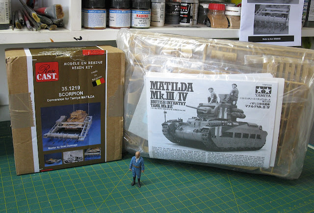 |
| Kojak, ready for action!!! |
 |
| Kojak among the pieces of the new project. The bald one loves a challenge... |
Well... here we go: following the instructions in the Resicast booklet, we must build the "host" kit up to a certain stage, and then we can start the transformation from the matilda gun to Matilda Scorpion. If that's the pie recipe, let's follow it!!! Starting with Tamiya's wonderful kit: wheels and suspension bogies. The parts are very well injected, with almost no burrs... A delicacy of the Gods!!!
 |
| Wheels and wheels... |
 |
| The suspension bogies built...no problems!!! Huzzah!!! |
 |
| Dude...those Tamiya kits are indecent... A delight to build... |
 |
| Everything fits perfectly, no adaptation problem... |
 |
| Construction is fast and smooth... |
 |
| Huzzah!!! |
 |
| I'm going to install the tracks, to facilitate the construction and alignment of future Scorpion props... left view |
 |
| Tracks in position right view |
And now, an intervention from the Resicast manual: in the booklet, they recommend using a 100 gr ballast at the rear of the tank, to balance the weight of the rotor of the trainers. For this, I will use fishing sinkers... Lead is ideal for this...
 |
| I made a wall with plasticard to contain the lead pellets... Using a food scale for an exact measurement... |
 |
| The important thing is that nothing is "shaking" or making noise... |
 |
| Exactly 100 grams of ballast!!! |
 |
| Using PVA glue to avoid "noise pollution"!! |
 |
| And closing the ballast chamber with a thin layer of plasticard, reinforced with a I-beam Plastruct |
 |
| Plastruct doesn't interfere with the upper deck... |
 |
| Perfect adaptation!!! Kojak, I salute you!!! |
 |
| Matilda's hull, with the 100 grams installed... Imperceptible, but heavy!! left view |
 |
| Matilda's hull, with the 100 grams installed... Imperceptible, but heavy!! right view |
 |
| Installing the side armored skirts... |
 |
| Now yes...a perfect Matilda is being born.... left view |
 |
| The Queen of Desert!! |
 |
| And with the turret, she simply looks stunning!!! The Queen!!! left view |
 |
| Right view |
 |
| Adding the details on the turret... Tamiya, you are fantastic!!! |
 |
| Right view |
 |
| The details on the turret, in close view... |
 |
| The Tamiya stage is practically ready!! |
 |
| The engine is very well cast in resin, with many details... Very well done, mrs. Resicast!! Uncle Ford approves!!! |
 |
| Using MacGyver as inspiration, let's make the spark plug wires going to the distributor... left view of the engine |
 |
| right view of the engine |
Some warped parts that will be fixed using the old tactic of dipping the piece in boiling water... When the resin softens, just rectify the position of the parts and wait for it to cool down...
 |
| The defects and the cure!!! |
The assembly of the trussed arm must be perfectly square. This delicate piece that only acquires resistance when fully constructed...
 |
| Checking the square... |
 |
| Checking the squareness, while we glue the diagonal crosspieces... |
 |
| And the structure of the left arm almost ready... |
 |
| Meanwhile, we paint the engine and provide the weathering of the entire structure... |
 |
| Notice that the engine has an air filter connected directly to the carburetor... This will decide the external shape of this structure... |
 |
| Applying the side shield of the rotor engine compartment... The side cover will not be installed, as the engine already has its air filter... |
 |
| Applying the upper engine compartment shield to the rotor... There are only the 3 air intakes. I'm not going to use the "Crusader" type filter that Resicast provides with the kit... |
 |
| The two arms of the Scorpion's flail rotor right view |
 |
| The two arms of the Scorpion's flail rotor left view |
 |
| Installing the two "I" type beams that will support the engine arm in its attachment to the shielded suspension skirt of the Matilda |
 |
| And the detail of the engine instrument panel, which was monitored by the flail operator. |
 |
| This image REALLY reminds me of Ripley, emerging from the armored hatch of the USS Sulaco´s belly: "Get away from her, you bitch!!!" |
But leaving science fiction for later (much later...), let's get back to the construction of flails, now. After cutting the "steel cables" to the specified length (the amount provided by Resicast is almost exact...be careful not to make mistakes...), I applied a minimal amount of superglue to the ends to "waterproof" the wire. This will speed up the gluing of the two "handles" at the ends of these wires...
 |
| All the "lower" handles glued (and dried...) in their places... Let's glue the "upper" ones now... |
 |
| Gluing the handle-shaped parts together to form the steel cable flails |
 |
| All flails made... |
And now, a change that I recommend: the Resicast Instruction Manual recommends that, when installing the chains on the ends of the steel cable flails, you cut a section in the resin part to fit the chain link. But cutting something so fragile really worries me... So I reversed the order of things: I decided to cut on the chain link, open that link with fine-tipped craft pliers and, after inserting the flail handle into the link, close the link metal with slight pressure. It is much easier to work with thin, flexible metal than a thin, brittle piece of resin. See the diagram below:
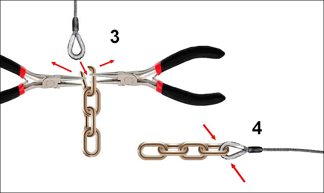 |
| 3- Using the two pliers, fit the link in the flail handle and... 4- return the link to its position, locking the chain in the flail. Zero breakage risk!! |
 |
| And doing this process on all Scorpion flails.... |
 |
| The flails ready for next step... |
 |
| I also replaced the rotor shaft (full of bubbles...) by a plasticard rod from Plastruct, in the correct diameter. Right side |
 |
| Left side. Much better... |
And with the rotor in position, the tedious step of gluing all the rotor clamps, fitting the flails onto these clamps, taking care to keep the flails mobile. The clamps, unfortunately, must be attached with superglue. Pay attention to the position of the clamps on the rotor, so that no clamp is in a strange situation when the rotor is at rest (obeying the good old Law of Gravity...).
 |
| And all the flails installed on the rotor, submitting themselves "normally" to the action of gravity... View with the vehicle in a rotary base... |
 |
| And the Scorpion in the ground, with the flails forward... |
 |
| And with the flails simulating Scorpion's movement to forward, dragging the flails in the terrain, with the rotor in rest... |
 |
| Very beautiful vehicle!!! |
 |
| Left view |
 |
| Rear right view |
And now, it's time to place our girl in time and space. After searching the deepest recesses of my library and the Internet, we found our Scorpion I in the western desert sands in preparation for the Second Battle of El Alamein in October 1942. Meet OLIVIER, a Matilda II Scorpion I of the 1st Army Tank Brigade, 42th Royal Tank Regiment, ready to clear a path through minefields in the dangerous African desert...
But, first of all, a nice bath of detergent, drying in the sun and in the wind and application of a light coat of light gray primer.
 |
| Light gray primer |
 |
| Color base (light stone) with tonal variations... |
 |
| A true desert girl!!! |
Whoops...I almost forgot about the rear poles and marker lights. Resicast wisely advises us to leave this stage for last, due to its fragility... and, therefore, it was being forgotten. But come on: really, the thing is very fragile. I decided to strengthen this detail a little, to avoid accidents. The first step is to replace the plastic pole with a much more resistant metal one. And to further increase the robustness of the whole set, I decided to "bury" the end of the metal pole in the rear fender of the tank, making a fair hole and very close to the Matilda's armored skirt. With that, I can fix the metal pole to the structure of the tank and, by sectioning the Resicast resin parts, gluing the pole protector parts to the pole and the base of the pole protector to the armored skirt. A minimal step will be formed in this piece, but once ready, the thing seems purposeful. we lost a micron of originality and gained a parsec of resistance!!! Kojak is a smart guy!!!
 |
| Panzerserra version of the Scorpion rear poles. |
Another small frisson: my kit didn't come with the parts for the small rear lights, perched on top of the poles, facing backwards. But the solution to this is easy and British correct: let's use the position lights from the AFV Club Churchills (H3 parts) left over from my countless builds. Well done, Old Chap!!
 |
| Notice the poles in position, with protectors, bases and rear lights installed. The parts painted in base color. Also note the application of decals on Scorpion: OLIVIER is being born... |
 |
| Rear view: 1st Army Tank Brigade 42th Royal Tank Regiment markings... |
 |
| Testing Tamiya's roll-bags in the turret rack, after a first coat of paint. They're not bad...I'll use them!!! Notice the tank name and census number... |
 |
| left view |
 |
| Front view, with 1st Army Tank Brigade 42th Royal Tank Regiment marking in the front glacis... |
 |
| Starting the weathering, with washing... |
 |
| One thing that bothers me is this empty space, on the "shoulder" of the left rotor arm. I honestly think it's a waste of space... |
But it seems I'm not the only one bothered: in 1943, someone decided to take advantage of this "crate" to transport things from the tank and the crew. Notice the photos below:
 |
| Matilda Scorpion I with "stuff" being transported in the left shoulder of the flail device Tunisia, Spring 1943. |
 |
| Matilda Scorpion II with "stuff" being transported in the left arm and shoulder of the flail device Egypt - late 1942 |
Bingo!! With these historical precedents duly recorded, we can add a few more details to our tank... In addition to using the original Tamiya crew (the loader was in an ideal position to be the flail operator) and the roll bags from the kit, we're going to add some Value Gear stuff and provide a sheet metal floor for the shoulder stuff (thin plasticard). Detail: don't think that the OLIVIER crew are crazy to take two American jerry-cans in a mine-flail: these jerrycans are for water (something very useful in the desert)!!
 |
| The metal floor in scratch and other stuff... The crew is perfect for the Scorpion!! |
 |
| The floor in metal and red oxide, welded in place... |
 |
| And all stuff in position. Notice the water jerry-cans (white W) and roll bags tied in place with leather straps... |
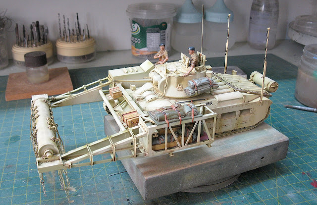 |
| A left side view of Scorpion, with crew in position and all details applied. |
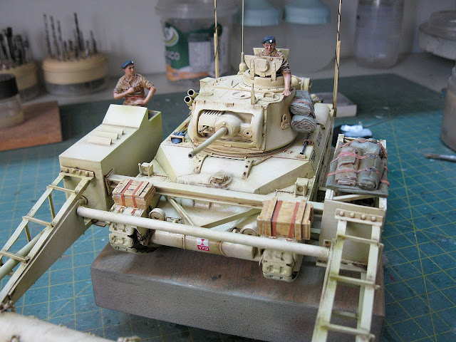 |
| The boxes on the front fenders are for spare flails and chains... |
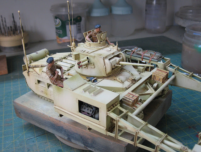 |
| The engine exposed... Is very hot in the desert!!! |
 |
| Starting the chipping...the desert It's a very abrasive environment!!! |
 |
| The kit is almost ready!!! |
 |
| Right view |
 |
| Rear view. Next: pigments... |
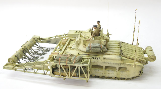
And with you, Matilda Scorpion I OLIVIER, from the 1st Army Tank Brigade, 42th Royal Tank Regiment, ready to clear minefields in the Second Battle of El Alamein, Western African Desert, in October 1942.
 |
Matilda Scorpion I OLIVIER 1st Army Tank Brigade - 42th Royal Tank Regiment Second Battle of El Alamein Western African Desert - October 1942. |
 |
| Matilda Scorpion I front left view |
 |
| Matilda Scorpion I left view |
 |
| Matilda Scorpion I left rear top view |
 |
| Matilda Scorpion I left rear lview |
 |
| Matilda Scorpion I right rear view |
 |
| Matilda Scorpion I right view |
 |
| Matilda Scorpion I right top view |
 |
| Matilda Scorpion I front right view |
 |
| Matilda Scorpion I with Kojak. |
 |
| Two desert beauties: Matilda Scorpion I with Crusader A15 cruiser tank Mk I - 2 pdr. |
 |
| Matilda Scorpion I front close up view |
 |
Matilda Scorpion I OLIVIER 1st Army Tank Brigade - 42th Royal Tank Regiment Second Battle of El Alamein Western African Desert - October 1942. |
Thanks for following!!!
Cheers!!


