Tankers !!!
While the
Heuschrecke 10 Grasshopper dry the decals (I hate waiting, doing nothing ...) , it's time to start a new project : the M6A1 American Heavy Tank, one of the forerunners of the modern main battle tanks.
History:
The Heavy Tank M6 was an American heavy tank designed during World War II. The tank was produced in small numbers and never saw combat.
 |
| An M5A1 and M6 in training. Note the comparative size of the tanks |
Because of limited budgets for tank development in the interwar years, at the outbreak of World War II the US Army possessed few tanks, though it had been keeping track of armor use in Europe and Asia. Successful employment of armored units in 1939 - 1940, mostly by the Germans, gave momentum to a number of US tank programs, including a heavy tank program. The United States possessed a massive industrial infrastructure and large numbers of engineers that would allow for mass production of tanks.
Following the Chief of Infantry recommendation from 20 May 1940, the
US Army Ordnance Corps started to work on a 50-ton heavy tank. Initially a
multi-turreted design was proposed, with two main turrets armed with low-velocity T6 75mm (2.95") guns, one secondary turret with a 37 mm gun, and a coaxial .30 caliber (7.62mm) machinegun, and another secondary turret with a 20 mm gun and a coaxial .30 caliber machine gun. Four .30 caliber machineguns were to be installed in ball mounts, two in the glacis plate and two in the rear corners of the hull. The project was approved on 11 June 1940 and the vehicle received the designation Heavy Tank T1. The design was somewhat similar in concept to multi-turreted breakthrough tanks developed in Europe in the 1920s and throughout the 1930s, such as the 1925 British
Vickers A1E1 Independent...
...or the Soviet
T-35 of the early 1930s. Disadvantages of these "land dreadnoughts", namely their excessive size, difficulty in coordinating actions of the crew, and high production costs, led to abandonment of the concept in Europe.
 |
| Soviet multi-turreted tank T-35 |
By October, the US developers reached the same conclusion as their European counterparts. The armament was changed to a single vertically-stabilized 3 inch (76.2 mm) gun and a coaxial 37 mm gun in a single three-man turret with both manual and electric traverse.
Originally it was planned to produce one prototype vehicle and to test in it four different types of power trains. But layouts indicated that hull changes would be required to accommodate each of these. Therefore two prototypes were authorized. One was to have a torque converter with a two speed manual transmission and the other a gasoline-electric transmission. The torque converter was a form of hydraulic transmission which applied the engine horsepower to the final drive in a variable torque speed ratio wherein the required ratio was selected automatically by the load placed on the vehicle. The gasoline-electric transmission involved a direct current generator driven by the tank engine. This furnished the electric current for a motor driving each track. Steering and braking were accomplished by varying the intensity of the current and by current reversal.
This transmission was so flexible that one track could be reversed while the other continued forward, causing the vehicle to spin on its own axis. The tank engine in each case was the 9 cylinder
Wright G-200 air-cooled aircraft engine of 825 hp.
The design laid out for the heavy tank was innovative in 1940. Both turret and hull were of cast armor, ballistic- ally well shaped and without side doors. The hatches were on top and there were escape hatches in the floor plate in the bottom of the hull. The final drive was in the rear, which provided more room in the interior. Track skirts were provided f or the suspension, the first modem U.S. tank to have them. The suspension was of the horizontal volute spring type.
 |
| horizontal volute spring suspension |
Power transverse and power elevation were included, as well as a gyro-stabilizer, the second vehicle to be so equipped, the first being an experimental installation of a gyro-stabilizer in acavalry combat car. The prototype TIE1 Heavy Tank with gasoline- electric transmission was completed first but the turret was only a makeshift one and the tank was never armed. The vehicle was used only for testing the transmission. During trials British observers followed the tests closely for comparison with the
British TOG tank which had a similar transmission. Speeds of 40 kilometers per hour were easily attained but the vehicle had only a 160 kms radius of operation.
 |
| British Tog II tank |
lt had been intended that the Tl have the torque converter but delays in manufacture caused the substitution of a hydramatic transmission in the prototype.
 |
| T1 prototype in 1/1 scale - wodden mock-up |
As previously mentioned, the turret carried a modified 3 inch
T9 antiaircraft gun with a coaxial
M5E1 37-mm gun. Two 50 caliber machine-guns were mounted in the front plate to be operated by the assistant driver and originally there also was a .30 caliber fixed machine-gun in the right corner of the front hull, operated by the driver ( how it was a fixed gun, his aim was taken by movement the tank ). There was a 30 caliber machine-gun in the turret cupola, like the
M3 Lee:
 |
| M3 Medium Tank - notice the cupola... |
The pilot-prototype TlE2 with the torque converter transmission was completed in December I941 and was standardized as the M6 Heavy Tank in February, I942. lt had a different turret with a .50 caliber antiaircraft machine-gun in the rear of the turret. Later, the main turret was changed.
 |
| T1E2 heavy tank pilot - Notice the turret with rear .50 machine gun |
The President’s program for production of munitions which had been announced in January 1942 called for the building of 500 heavy tanks in 1942 and 5000 in 1943. After standardization of the M6, contracts were let with
Fisher Body Division of General Motors Corporation and
Baldwin Locomotive to build them at a combined rate of 250 per month.
In 1941 - 1942 three prototypes were built by the
Baldwin Locomotive Works, one with electric transmission and two with torque converter transmission. Variants with hydramatic transmission were never completed. The prototypes also differed in hull assembly method - one had welded hull and two cast hull. On 26 May 1942 two variants with torque converter transmission were standardized as M6 and M6A1.
 |
| T1E3 / M6A1 - Welded hull - front left view |
In April 1942, because of shortcomings discovered in testing, there was a complete redesign of the brakes and the cooling system. Between delivery in December and April I942, the vehicle had covered 5.600 kms un the
original set of tracks and 1.600 kms more on the second set.
The new brakes adopted were of the type which had been
developed for railroad trains operating over the mountains in the westem part ofthe United States. They were
hydraulically actuated disc type brakes applied to the
controlled difierential.
In spite of the good showing made by the M6. the
Armored Board objected to the letting of contracts and
announced that the vehicle was unreliable and over-
weight and that they did not want it.
 |
| M6 Heavy Tank - schematic cutaway |
Although Ordnance
repeatedly olfered to eliminate the weaknesses. Army
Ground Forces concurred with the Armored Force.
The Army Supply Program of September 1942 cut the
production requirements to 115, 50 of which were to go
to the British. The Fisher Body contract was cancelled
and the balance of the order was to be produced by
Baldwin Locomotive.
Two production pilots of the M6
were delivered in December, but on December 7 the
Chief of the Armored Force stated that there was no
longer any requiretttertt and recommended that production be stopped immediately. Army Ground Forces
concurred. The British also agreed because they had
wanted the M6 for North Africa where there would be no
bridge problem and now. at the beginning of I943. the
end of the campaign in North Africa was in sight.
As a result. only the following had been produced by
early in I943 when production ceased:
- 0l - T1: with hvdramatic transmission. cast hull and turret
- 19 - T1E1(M6A2):gasoline-electric transmission, cast hull and turret
one being the original prototype
- 08 - TlE2 (M6): cast hull. cast turret. torque converter
- 12 - T1E3 (M6A1): welded hull. cast turret. torque converter
Of the 40, only 12 were made by Fisher Body Division
and the rest by Baldwin Locomotive. A T1E4 with
welded hull, cast turret, four diesel engines and two
torquematic transmissions had been contemplated but
it never materialized.
However by the time the M6 was ready for production, the Armored Corps had lost interest in the project. The advantages the M6 offered over medium tanks - its much thicker armor and slightly more powerful gun - were offset partly by the shortcomings of the design - such as very high silhouette, awkward internal layout and reliability problems - and partly by logistical concerns. By the end of 1942, the Armored Corps were sure that the new
M4 Sherman gave adequate solution for the present and the near future, while being reliable, cheap and much easier to transport.
Work on the M6 didn't stop at once. The T1E1 prototype was tested with a T7 90 mm gun and was found to be a satisfactory gun platform, although poor turret layout was noted again.
 |
| T1E1 heavy tank - front view |
 |
| T1E1 heavy tank - rear view |
In August 1944 the Ordnance Corps recommended using the T1E1s produced to build 15 77-ton vehicles designated M6A2E1.
 |
| M6A2E1 |
 |
| M6A2E1- turret rear view |
The M6A2E1 presented a thicker (up to 190 mm vertical protection) glacis armor and a turret developed for the
T29 Heavy Tank, armed with a T5E1 105 mm gun.
 |
| T29 American heavy tank |
The proposal was rejected by
General Eisenhower. However, by late 1942 main development effort shifted to other projects, one of which eventually resulted in the
M26 Pershing.
 |
| M26 Pershing |
On 14 December 1944 the M6 was declared obsolete. Only forty units were produced and they never left US soil. Several toured the United States for propaganda purposes, where they gave performance displays (such as car crushing) at War Bond drives and the like.
 |
| Dragon's box art - car crushing job !! |
All were eventually scrapped except for a single T1E1 which is on display at the
United States Army Ordnance Museum,
Aberdeen, Maryland.
Although the M6 tanks never saw combat, some of their forward looking features were applied to other tanks. Cast, and later welded, armor was used in the M4 series. The gyro stabilizer and power traverse were used in both the M3 and M4 Medium Tanks. The horizontal volute spring suspension was applied experimentally to several tanks and then to all medium tanks. The gasoline-electric transmission was used in the
T23 Medium Tanks,
 |
| T23 medium tank |
The hydramatic transmission was applied to the
M5 Light Tank and the torque converter was used in the
M18 Hellcat GMC.
 |
| M5 light tank, fully restored. |
 |
| M18 Hellcat, fully restored |
And the suspension and tracks were used in one of the versions of the British
A33 Heavy Tank.
 |
| British heavy tank A-33 Excelsior |
Thus it cannot be said that the design of the M6 was a waste. The attitude of the Armored Force initially was due to the feeling that too much shipping space was required for these giants, in that two Shermans could be loaded in the same space. But their continued opposition and later reversal of opinion perhaps can be explained only by the familiar problems of personalities and power politics.
Variants:
- T1 - Cast hull, hydramatic transmission. 01 built.
- T1E1 - Cast hull, electric transmission. Often unofficially referred to as M6A2. 19 units built.
- T1E2 / M6 - Cast hull, torque converter transmission. 8 units built.
- T1E3 / M6A1 - Welded hull, torque converter transmission. 12 units built.
- T1E4 - Welded hull, hydramatic transmission. Never built.
- M6A2E1 - Uparmored T1E1 with a new turret armed with a T5E1 105 mm gun. Used for testing T29 project armament system.
Specs:
| Heavy Tank M6 |
|---|
| Place of origin Type | United States
Heavy tank |
|---|
| Service history |
|---|
| In service | trials only |
|---|
| Used by | United States Army |
|---|
| Wars | World War II |
|---|
| Production history |
|---|
| Designer | US Army Ordnance Corps |
|---|
| Manufacturer | Baldwin Locomotive |
|---|
| No. built | 40 |
|---|
| Variants | 6 |
|---|
| Specifications (M6) |
|---|
| Weight | 57.4 tonnes combat loaded |
|---|
| Length | 8.43 m gun forward |
|---|
| Width | 3.12 m over track armor |
|---|
| Height | 3.0 m to turret roof |
|---|
| Crew | 6 (commander, gunner, driver, assistant driver, l
oader, assistant loader) |
|---|
|
| Armor | 25–83 mm |
|---|
Main armament
| 1 × 76.2 mm gun M7
(75 rounds)
1 × 37 mm gun M6
(202 rounds) |
|---|
Secondary armament
| 2 × 12.7mm Browning M2HB mgs, hull
(6,900 rounds)
2 × .30 Browning M1919A4 mgs - bow & flexible AA (5,500 rounds) |
|---|
| Engine | 29.88 LWright G-2009-cylinder gasoline
825 hp at 2,300 rpm |
|---|
| Power/weight | 15.7 hp/tonne |
|---|
| Transmission | Timken mechanical model 16001, three speeds (two forward, one reverse);
rear drive sprocket |
|---|
| Suspension | Horizontal volute spring |
|---|
| Ground clearance | 52 cm |
|---|
| Fuel capacity | 1,810 L |
|---|
Operational range
| 160 km |
|---|
| Speed | 35 km/h |
|---|
The kit:
For this project, I'll use the new Dragon Black Label #6789 M6A1 Heavy Tank.
 |
| Dragon's box kit |
When this kit was released, a lot of criticism rained down about the discrepancies of the model, especially the turret impeding the hatch opening of the auxiliary driver, when aligned in forward position. Indeed, this is a huge mistake!!
 |
| The turret closing the hatches...Eeewww!!! |
By observing the contours of the tower and its positioning in the hull, we realized that the shape of the turret is wrong and its position in the upper-hull slightly forward.
 |
Composite image (bird view) between the real M6A1 and the Dragon's kit:
1- The turret in wrong position in the upper-hull: slightly forward;
2- Comander hatch in position slightly forward, too;
3- Left lateral contour of the turret wrong;
4- Right lateral contour of the turret wrong;
5- Aerial base advanced in the turret's roof |
But the corrections are simple to execute: just a bit of plasticard, putty and a pound of engagement. I'm not a riveter counter, but this turret is awful !!! Surgery time!! First of all, printing a guiding image:
 |
| The Dragon's turret... |
 |
Schematic drawing of the cuts to be performed in the commander's
hatch to reposition the piece |
 |
Cutting the roof of the tower around the hatch
with Dremel and steel disk. Watch your fingers !!!
|
 |
| After the hatch removed, cut portion to allow retreat. |
 |
| Cutting the part |
 |
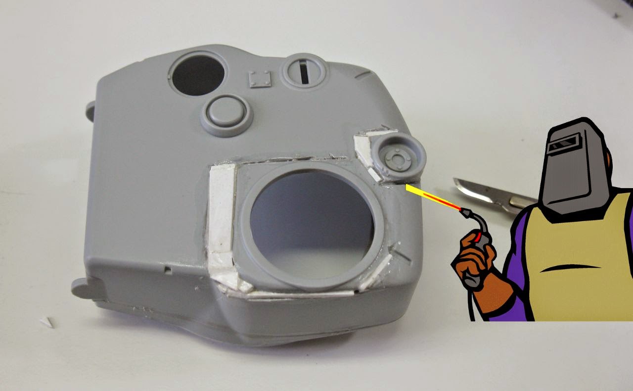
| Cutting the aerial base for new positioning... |
 |
| Surgery almost done... |
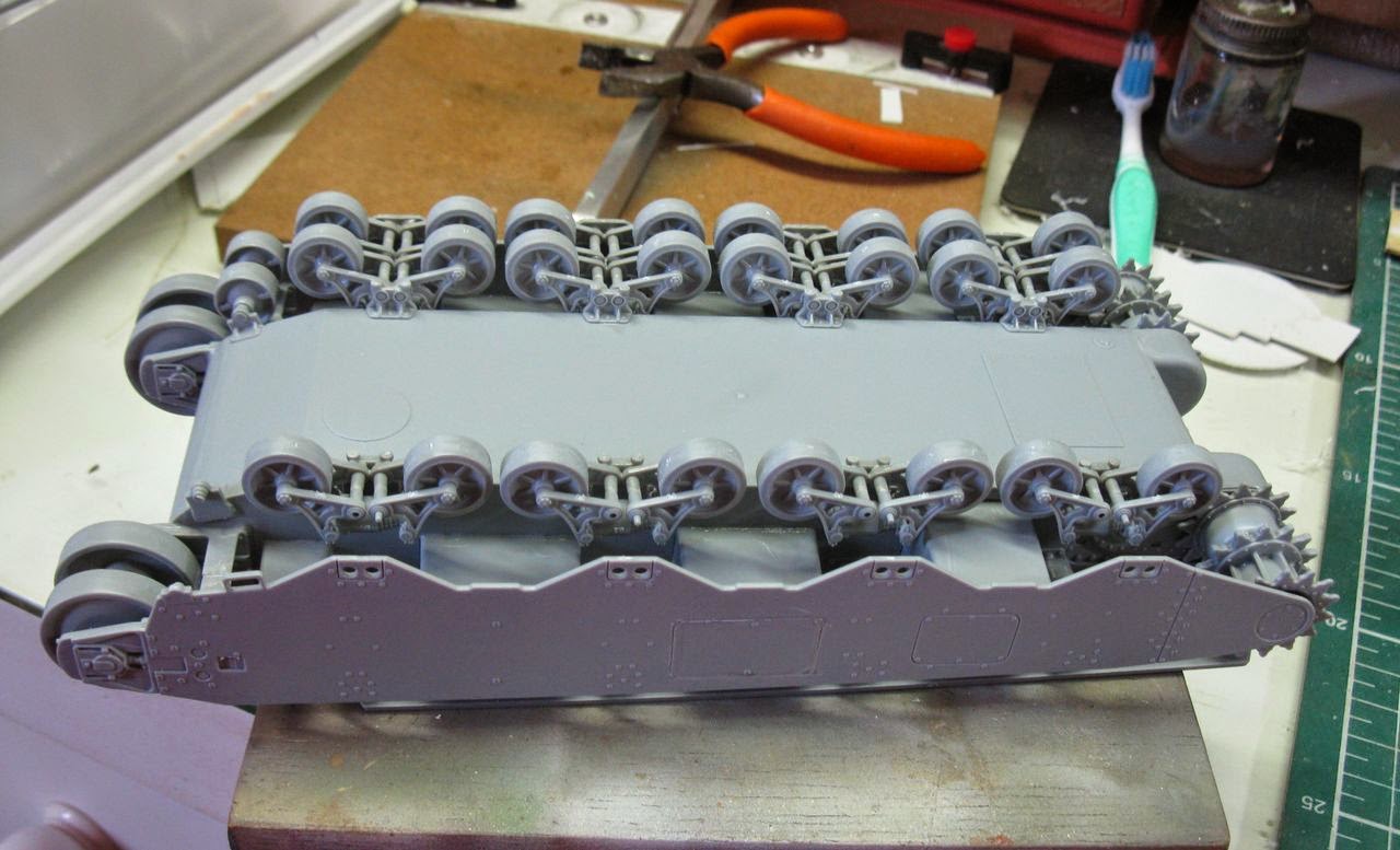
But let's start the building, by the book: suspension and wheels!
 |
| A boring job: clean all parts !!! |
 |
| Internal bogies - right side |
 |
| Internal bogies - left side |
 |
| spacers... |
I built the external bogies in a different way of the instructions: First, I built the side armour plate...
 |
| Side armour plate in position... |
Then, I fit the external bogies entering first the external pins on the side armor ...
 |
| Introducing the bogie by spin ... |
And so, introducing the internal pins of the external bogie in the holes of the internal bogie!!!
 |
The bogie's external pins in the armour (red arrows) and
the internal pins in the holes of the internal bogie (blue) |
 |
| Done !! |
 |
| Starting the other side... |
 |
| Attaching and rotating... |
 |
| The rotating movement... |
 |
| testing the alignment of bogie's arms ... |
 |
| Changing the plastic 37mm by metal one (by RB Models) |
 |
| Dry-run: too long !!! |
 |
| Metal surgery !!! |
 |
| Chuck approves !!! |
 |
| The basement of the .50's with motion... |
 |
| Eyes up!! |
 |
| Eyes down !! |
 |
| Changing the plastic by metal, again... |
 |
| Movement !!! |
 |
| Down !! |
 |
Using putty to increase the casting texture of the turret
and front armour - left view |
 |
| right view |
 |
| right top view |
 |
| The Commander hatch open... |
 |
..and close: I used a very sharp drill and acupuncture needle
(which also served as antennas) |
 |
| Almost ready for painting... |
 |
| Wiring in the rear lamps... |
Now, the best part: painting the kit...A color profile as guide:
 |
| Olive drab pattern with tonal color variations... |
 |
| front left view |
 |
| front right view |
 |
| rear right view |
After the Future, applied with airbrush, decals from my spare parts box:
 |
| Notice the tracks, in position... |
 |
| Left view |
 |
| rear view |
 |
| Right view |
And I was almost forgetting the .30 Browning MG fixed in the front hull. The kit does not show this detail. I did the .30 with a surgical needle.
 |
| M6 armament (the M6A1 was the same) |
 |
| The huge girl, armed and more dangerous... |
Thank the Gods, my cold was gone and I was able to finish this great lady ...Loved the building of the M6A1 and the correction performed in the tower really made me happy with the results.
 |
| M6A1 American Heavy Tank |
 |
| M6A1 American Heavy Tank |
 |
| M6A1 American Heavy Tank - left side |
 |
| M6A1 American Heavy Tank - left rear view |
 |
| M6A1 American Heavy Tank - rear view. Notice Value Gear stuff |
 |
| M6A1 American Heavy Tank - rear right view |
 |
| M6A1 American Heavy Tank - right side |
 |
M6A1 American Heavy Tank
right view |
 |
M6A1 American Heavy Tank
right front top view |
 |
M6A1 American Heavy Tank
right front view |
 |
M6A1 American Heavy Tank
front top view |
 |
M6A1 American Heavy Tank
left front top view |
 |
M6A1 American Heavy Tank with
Kojak and Rover, the dog. |
 |
M6A1 American Heavy Tank with Sherman VC Firefly
for size comparison |
 |
M6A1 American Heavy Tank with Sherman VC Firefly
for size comparison - side view |
 |
M6A1 American Heavy Tank with Sherman VC Firefly
for size comparison - front view |
 |
| M6A1 American Heavy Tank |
I loved this makeover project... Although the kit was nice and well detailed, the defects reported pretty much require you to fix them and I loved doing that...it was a lot of fun.
Expect a new project, soon !!!!