
Ladies and Gentlemen!
Today's character is a medium tank, which was designed by the British in the fertile period of ideas of the 20s and 30s, being one of the examples of mechanized warfare in the so-called inter-war period. With you, the Vickers Medium Mk.III tank.

History:
The Medium Mark III, also known as Vickers Medium Mk.III tank was a medium tank developed in the United Kingdom during the Interwar period.
 |
| Vickers Medium Mk.III tank |
The prototypes of the Medium Mark III were the three A6 also known as "16-tonner" tanks. From the tests of the A6, only three Mark IIIs were built and put into service with the British Army but due to the high cost no more were purchased.
Development:
In 1926, the British War Office wanted to replace their existing Mark II tanks with a new design. In May the Royal Tank Corps Centre was asked for its opinion, which it submitted in July. One of the requirements was a weight limit of 15.5 long tons (15.7 t), which led to the nickname "16-tonners".
 |
Vickers Medium Mk II tank of the Royal Tank Regiment on manoeuvres at Bovington Camp, Dorset - UK - November 1939 font: IWM - H 233 |
Other specifications included that it could transported by rail, a sufficient supply of lubrication oil to match the range of the tank (dictated by the fuel carried), a wireless set, a gun capable of defeating enemy armour at a range of at least 910 m, fuel tanks external to the main compartments and bottom armour sufficient to withstand heavy machine-gun fire, when exposed climbing a crest. Furthermore the machine should be as silent as possible, as with previous types the engine noise tended to incapacitate the crew. The British War Office added some extra requirements: a separate engine compartment; superior steering capacity and 13 mm frontal armour with 9 mm thickness for the other plates.
In September, 1926, Vickers given the order to build a prototype, proposed a first design based on the Vickers A1E1 Independent, with the fighting compartment in front and the engine compartment at the back.
%20IWM%20KID%20109.jpg) |
| Vickers Independent Heavy Tank (A1E1) font: IWM KID 42 |
There would be a central two-man turret with a QF 3-pounder (47 mm) gun and a coaxial machine-gun; it was intended to house the commander and a 'special observer', with a cupola for each. In the front of the hull were to be placed two secondary machine-gun turrets, each with twin Vickers machine guns.
 |
| Closeup of QF 3 pounder (47mm) gun in a Vickers Mk.II tank Royal Australian Armoured Corps Tank Museum Puckapunyal - Victoria - Australia. |
A third machine-gun turret was intended to be mounted at the back of the vehicle, behind the main turret, which would be armed with an anti-aircraft (AA) weapon. A crew of seven men was needed. Maximum armour would be 13 mm and basis armour 6.5 mm, limiting the weight to 14 tons. Riveted plates were used. The total fuel supply would be 550 L: 45 liters in a small tank inside, gravity feeding the engine; the remainder in external tanks on the fenders. Two engine options were indicated: a 120 hp (89 kW) engine would allow for a speed of 23 km/h and a 180 hp (130 kW) engine would raise this to 32 km/h.
The result was give the General Staff number A6. In March 1927 a wooden mock-up was presented and after approval a second and prototype were ordered which had to incorporate the new hydraulically operated Wilson epicyclic steering gearbox, the predecessor of the Merrit-Brown gearbox. By June 1928, A6E1 and A6E2 were presented to the Mechanized Warfare Experimental Establishment for trials. Vickers was on this occasion ordered to add armour skirts but keep within the weight limit even if it meant removing armour elsewhere; A6E3 had also been ordered.
%20IWM%20KID%20617.jpg) |
| Medium Tank Prototype A6E1 font: IWM KID 617 |
%20IWM%20STT%201674.jpg) |
| Vickers Medium Tank A6E2 prototype and Vickers Independent Tank (A1E1) font: IWM STT 1674 |
 |
| Vickers Medium Tank A6E2 prototype Notice the nº 2 in the driver´s station font: IWM KID 4490 |
%20%20IWM%20KID%20276.jpg) |
| Medium Tank Prototype A6E3 Note the arrangement of the suspension elements, completely modified in relation to the two previous models font: IWM KID 276 |
The A6E1, A6E2 and A6E3 were fitted with an Armstrong Siddeley air-cooled V8 180 hp engine giving a maximum speed of 26 mph (42 km/h). A6E2 was fitted with the Ricardo Compression Ignition 180 hp engine but this was not satisfactory and the Armstrong-Siddeley was refitted. A6E3 was later re-engined with the Thornycroft 6V 500 hp (370 kW), a slow revving marine engine. It was proposed to combine two Rolls-Royce Phantom engines with the Wilson transmission system on the A6E1 but this was rejected on grounds of expense. A6E2 was eventually refitted with the Armstrong Siddeley V8 180 hp.
 |
| Vickers Medium Tank Mk.II and the Vickers A6E2 Medium Tank. font: IWM STT 1670 |
 |
| Vickers Medium Tank Mk.II and the Vickers A6E2 Medium Tank, side by side font. IWM STT 1672 |
In photographs of the vehicles, some differences can be noticed between the three prototypes: in prototype nº 1 (A6E1), we can notice a small triangular-shaped reinforcement detail, in the region of the last return roller of the suspension (red arrows). This structural reinforcement is much bigger in prototype nº 2 (A6E2) and absent in the completely modified suspension of the model nº 3 (A6E3). Another difference is the support wheel in the front portion of the track, with a large diameter (green arrows) in model nº 1 and model nº 2, although in some photos (such as the example), this larger wheel has been replaced by two smaller ones, in the form of a two-wheeled bogie, which is present in later photos of model nº 2 and tank nº 3 (A6E3). Models nº 1 and nº 2 are very similar, with an opening on the side of the suspensions, in an irregular hexagonal shape, for an escape hatch (blue arrows). This detail is non-existent on model nº 3, with a much more different suspension than previous versions. These details can be seen in the photographic montage below:
 |
| The 3 prototypes: A6E1, A6E2 and A6E3 |
The guns were tested in July 1928 and proved that the twin-machine gun arrangement was unworkable, due to the difficulty in feeding the ammunition.
 |
| Medium Tank Prototype A6E1 - 1928 Note the double machine guns on each front turret. The proximity between the weapons made it difficult to feed the machine guns... See also the absence of the coaxial MG in the main turret, in this pic. |
The A6E3, under construction, was fitted with a simplified design with a single machine-gun; it also had single cupola on the centreline of the turret. The AA-turret was removed from A6E1 but the suspension and the gunnery arrangements were distinctly inferior to those of the Mark II. It was decided to discontinue the type and use the three vehicles as test-beds for the automotive parts. In 1929, Vickers submitted three alternative suspension designs which were fitted to the respective prototypes; the one on A6E3 involved a fundamental reconstruction of the hull but none of the designs provided a stable gun platform. Only in 1934 was a satisfactory type was fitted by a specialised firm.
%20%20IWM%20KID%202174%20big.jpg) |
| Medium Tank Prototype A6E1 front right view June, 1928 |
%20IWM%20KID%20165.jpg) |
| Medium Tank Prototype A6E1 rear left view font: IWM KID 165 |
| A prototype of Scammell Pioneer tank transporter with carrying a Medium Tank prototype A6E2 for trials in the field - 1929 font: IWM KID 2760 |
| Another angle of Scammell Pioneer tank transporter prototype with Medium Tank prototype A6E2 for trials in the field - 1929 font: IWM KID 4092 |
%20under%20trials.jpg) |
| The Medium Tank prototype A6E2 destroying a double brick wall, in a field test. This is a typical photo of any new tank test... |
The prototypes A6 did not perform as satisfactorily as expected, either in terms of armament or stability, with the suspensions being their biggest problem. In short, the vehicle was not considered superior enough to the Vickers Mark II to justify a definitive production order. After so much investment in the development of the A6 prototypes, the Vickers Armstrong, in an attempt to revive the concept of the 16-ton multi-turreted tank, designed a vehicle based on the A6, but intensely improved, in 1928.
This new tank, similar to A6 ones, featured improved armor, with 14 mm at the front and 9 mm around, as well as a new main turret. The two secondary turrets were maintained, but repositioned. The tank also retained the rectangular hatches on the hull sides of the first two prototypes. According to the literature, such hatches were developed to allow the removal of seriously injured crew members using a stretcher, without subjecting the injured person to vertical removal through normal hatches. The new tank was called Vickers Medium Mark III.
Birth of Vickers Medium Mk.III tank
The Vickers Medium Mark III being ordered in 1928 and constructed from 1930. The main turret had a flat gun mantlet and a bulge at the back to hold the radio set.
 |
| Vickers Medium Mk.III drawing - main turret via Loris Visintini (thanks for the drawings, my friend!) |
The secondary machine-gun turrets were moved more to the front to shift the centre of gravity of the vehicle forward to improve its stability and larger brakes were fitted. The driver's station was between the two secondary turrets, in a central and forward position on the hull.
 |
| Vickers Medium Mk.III drawing - driver station via Loris Visintini |
 |
A brand new Vickers Medium Mk III in the Vickers-Armstrong factory - 1929 font:IWM KID 4625 |
 |
| The Vickers Medium Mk III - 1929 Notice the secondary turrets and the rear bulge on the main turret, for the wireless. font:IWM KID 2561 |
Three Mark IIIs ( E1, E2 and E3) were built, one by Vickers and two by the Royal Ordnance Factory at Woolwich.
 |
| Vickers Medium Mk.III drawing - left and rear view via Loris Visintini |
Many field tests were carried out between the years 1930 and 1933, with more positive results than the A6 prototypes. The Medium Mk.III was considered more reliable, offering greater comfort to the crew and behaved as a more stable firing platform than the operational Marks I, II and the A6 prototypes.
 |
| Vickers Medium Mk.III drawing - internal arrangement via Loris Visintini |
But the big problem was still the suspension, which despite all the work put into improving it, was overloaded and the track components wore out quickly when used in off-road conditions.
 |
| Vickers Medium Mk.III drawing - chassis and suspension bogies via Loris Visintini |
Finally, the 3 finished vehicles were acquired for use by the Royal Tank Corps and in 1933 they entered service as HQ tanks.
 |
| Front view of Vickers Medium Mk III (E3) Notice the access hatches to the driver's station, the absence of machine guns and the camouflaged paint in what appears to be in two tones - UK - 1933 |
%20Andrew%20Hills%20-%20protective%20cowls%20over%20the%20headlamps.jpg) |
Vickers Medium Mk III E1 (MT 9707) used as command vehicle, before installing the clothesline antenna surrounding the turret. Note the two-color camouflage paintwork and the rectangular protections over the front headlights. - UK - 1933. picture via Andrew Hills (thanks a lot, my friend!) |
 |
| rear view of Vickers Medium Mk III (E3) via Loris Visintini |
 |
| Vickers Medium Mk.III tank E3 (MT 9709) negotiating a ridge, in rough terrain. Salisbury Plain maneuvers – 12 August, 1934. |
These vehicles were used prominently in one of the largest combined arms training exercises of the time, on Salisbury Plains, on 12 August 1934. They acted as command tanks alongside other experimental armored and mechanized forces of the British Army. They were used by Brigadier Percy Hobart in those maneuvers.
 |
| Frame of a Pathe Gazette newsreel showing the Vickers Medium Mk.III tank E3 (MT 9709) in manoeuvres with 1st Tank Brigade - Royal Tank Corps on Salisbury Plain maneuvers - 12 August, 1934. font: IWM 1064-02d |
 |
| Another frame of a newsreel showing Vickers Medium Mk.III tank E3 (MT 9709) with Medium Mk.II ,in manoeuvres with 1st Tank Brigade - Royal Tank Corps Salisbury Plain maneuvers -12 August, 1934. font: IWM 1064-02d |
 |
| Vickers Medium Mk III E1 (MT 9707) used as command vehicle Salisbury Plain maneuvers - 12 August, 1934 font: IWM MH 8102 |
 |
| Officer of the Royal Tank Corps briefs his men before a military exercise. He stands next to a Vickers Medium Tank Mark III E1 (MT 9707) which is being used as his command vehicle Salisbury Plain maneuvers - 12 August, 1934 font:IWM MH 8101 |
 |
| Vickers Medium Mk.III tank E3 (MT 9709) at full speed in the field - late 1934. |
 |
| Vickers Medium Mk.III tank E3 (MT 9709) in rough terrain - late 1934. |
 |
| Vickers Medium Mk.III tank E3 (MT 9709) under maintenance in the field - late 1934. |
 |
| Vickers Medium Mk.III tank E2 (MT 9708) under maintenance in the field - 1934. |
Shortly after the exercise, one tank (E1 - military registration MT 9707) was written off, another was destroyed in a fire (E2 - military registration MT 9708) in September of 1934 near Swindon, and the sole survivor E3 - military registration MT 9709) remained in service around the training ground until 1938, and was likely scrapped some time in the crazy years of 1939-40, to reuse material.
 |
| Vickers Medium Mk.III drawing - left side view via Loris Visintini |
As a result, unfortunately none of these elegant and slender machines have survived to this day.
Specs:

| Vickers Medium Mk III tank | |
|---|---|
| Type | Medium tank |
| Place of origin | United Kingdom |
| Service history | |
| Used by | British Army |
| Wars | none |
| Production history | |
| Designed | 1930 (A6 – 1926) |
| Manufacturer | Vickers-Armstrong Royal Ordnance Factory |
| No. built | 3 |
| Specifications | |
| Mass | 16 tons |
| Length | 6.55 m |
| Width | 2.67 m |
| Height | 2.79 m |
| Crew | 7 |
| Armour | 9-14 mm |
Main armament | 3 pounder gun |
Secondary armament | 3 × 0.303 (7.7 mm) Vickers machine guns |
| Engine | Armstrong Siddeley air-cooled V8 180 hp (130 kW) |
Operational range | 190 km |
| Maximum speed | 48 km/h |
The kit:
For this commisssion work, I will use a kit from a manufacturer that is still new to me: the SSModel, from China. The 3D printed kit Vickers Mk.III British Medium Tank (#35579).
 |
| SSModel 3D printed kit Vickers Mk.III British Medium Tank (#35579). New box art |
But my client got this model on eBay, with the "early" version of the box:
 |
| SSModel 3D printed kit Vickers Mk.III British Medium Tank (#35579). Old box art |
 |
| The bald one at the workbench, with SS Model box kit |
 |
| And Kojak along with the contents of the box... Ouch...many broken parts, on first inspection... |
The "Assembly Instruction Manual" is a true tragedy:
 |
| The kit represented is not the same as the one in the box (thankfully...) |
The worst: the rear fenders are fractured and without the broken parts in the plastic bag... It shows that the hull was packaged already fractured, although some parts, such as the exhaust mufflers, are in bags. Hell!!!

 |
| Notice the rear fenders broken. No broken parts or fragments of this in the box!!! |
 |
| In addition to the fractured rear fenders, the rear deck extensions and the rear central tie-down hook... |
 |
| Front right headlight (this was in the box...) broken |
 |
| Fracture of two links of the right suspension track. The pieces were in the box, but not complete... |
 |
| Both sets of suspensions have more curves than our dear Marilyn!!! |
 |
| Phew...a little relief: the main turret looks perfect. very well printed and WITHOUT PRINT LINES (Hallelujah!!!) Congratulations, SS Models!!! |
 |
| The two front auxiliary turrets also... |
 |
| More positive things: the tow hooks and the front ladder are very well printed and protected by an efficient roll cage... |
 |
| And that's the icing on the cake: two cannon barrels!! Excellent attitude, SS Models!!! Chuck approves!!! |
 |
| But back to the defects: the broken parts of the rear deck, with a printing flaw in the exhaust angle... Notice the front headlight and the rear lamp. |
 |
| After gluing the two suspension links, we have missing parts to be done. Not a big deal, but a pain!!! |
But now, one thing that is really DISGUSTING in some 3D printed kits: the resin appears to not be fully cured and the damn delaminations... This is unforgivable!!!
 |
| Delaminations!!! I hate this!!! The luck is that the most affected parts are internal.... |
 |
| Delaminations affected both suspension assemblies... |
 |
| Wheels, bogies, ouch...This is disgusting!!! |
 |
| Even more disgusting (it's hard to hold back the vomit...) are the uncured portions of resin. These parts secrete a liquid that is really worrying... The good news is that the layer of cured and healthy resin is very thick!!! |
 |
| More portions with poorly cured resin (main turret - internal roof) |
And now, a flaw in the kit's design: the correct location of the two front auxiliary turrets is not marked on the tank chassis. The turrets are installed in the front portion of the deck, but EXACTLY where the manufacturer did not bother to demarcate. This is a glaring flaw, as turrets allow for random placement. A modeler with little experience will have a lot of difficulty at this stage...
 |
| Front auxiliary turrets: where the hell are they, exactly??? |
 |
| No markings, "neck", elevation, nothing!!! |
 |
| The turrets have an excellent circle for a neck fit, but SS Models thought this would be unnecessary... Shame on you, SS Models!!! |
 |
| Multiple possibilities for error.... |
 |
| ...and no fitting marks at all!!! |
 |
| Really, absurd... Let's base ourselves on the original photos to try not to make mistakes... And speaking of which, the instruction manual makes the strongest cry: a simple poorly printed and poorly detailed sheet!!! |
For these and other reasons, the kit starts to irritate you when building it. Instead of being a pleasurable experience, everything reflects that it is a product that is produced anyway, without care for the packaging or the end consumer. the printing details are EXCELLENT...the best I've seen so far in 3D kits...but the overall work is a little disappointing...but let's make lemonade out of these lemons; life is not easy and the Vickers Medium Mk.III is a vehicle that deserves to be reproduced... and we will achieve that!!!
 |
| Hell!!! Here we go!!! Let's see who can do it the most!!!! |
Well... the first thing to do is straighten the suspension assemblies. I immersed each set in boiling water, left it for a few seconds and placed the pieces on a flat surface, with some counterweights, to maintain the new position...
 |
| The suspensions, after the hot bath!!! |
 |
| And goodbye warped suspensions!! Chuck is satisfied!!! |
I noticed a small gap in the front portion of the front hull, on its left side. I think it was a printing error... As things were very discreet, I applied a thin plastic sheet (0.3mm thick) directly over the defect, correcting it. No big deal... just 10 minutes of work...
 |
| The plastic sheet (0.3mm thick) in position. I removed the headlight carefully, so I could later return it to the same position. |
While the front portion dries, let's take care of the rear fenders. Here I used fragments of the 3D print with the same thickness as the fenders. I cut some excess pieces, glued them with superglue and then I will rectify their dimensions with my sanding discs installed on my Dremel.
 |
| Gluing fragments of the 3D print of the same thickness as the fenders. |
 |
| I sanded the gluing areas and sanded the edges with my sanding discs! |
 |
| Using plastic cards from old magnetic cards, I redid the two rear fenders. A satisfied Chuck Norris is priceless!!! |
Another flaw in the kit's engineering: THERE ARE NO MARKINGS FOR INSTALLING THE SUSPENSIONS!!! The turrets were installed based on the original photos... as will the suspensions. What an ugliest thing, Mrs. SS Models!!!
 |
| Where to install the suspensions?/ Distance?? Height?? Here's a dry-run using a template below the chassis, to a standard height. Right view |
 |
| Dry-run with suspensions. Left side. |
I used a 15mm styrofoam plate, as template, which I cut in a regular shape, supporting the chassis at that height. With this, I was able to glue the suspensions, aligning one of the return rollers with the angle of the upper deck. Uffff!!!
 |
| The styrofoam template in place... front view. Notice the left headlight in the front fender. |
 |
| I used gel superglue, to allow longer gluing time, allowing for some adjustment... Perfect!!! |
 |
| Left suspension glued in position!!! |
And while the suspensions are sticking, let's build a locking mechanism for the turret, which allows it to rotate without the risk of it falling. I will use the same system that I used on Matilda I, but with the difference that I will apply a plasticard disc to the lower portion of the tower, in order to allow the installation of a long screw on this base... Look at the photos:
 |
| Cutting the 1mm thick plasticard with a dry point compass! |
 |
| Increasing the thickness of the turret disc with a piece of Plastruct scrap with 2mm thick. |
 |
| The 1mm disc glued to the base of the turret.(it's upside down)... I placed a guide in the center of the disc to make it easier to insert the screw... |
 |
| While the turret disc dries, we install the exhaust pipes and mufflers on the rear deck. Kojak wastes no time.... Notie the rear lamp in position... |
 |
| All in place. It's quicker to redo it from scratch than to order a new part from SS Models... |
 |
| The Vickers Medium Mk.III looks very good!!! |
 |
| These 20s girls are so stylish!!! |
 |
| The "discreet" screw that will allow the turret to rotate in position... |
 |
| The hole in the base of the chassis, as well as the countersunk recess to allow the screw head not to stick out... |
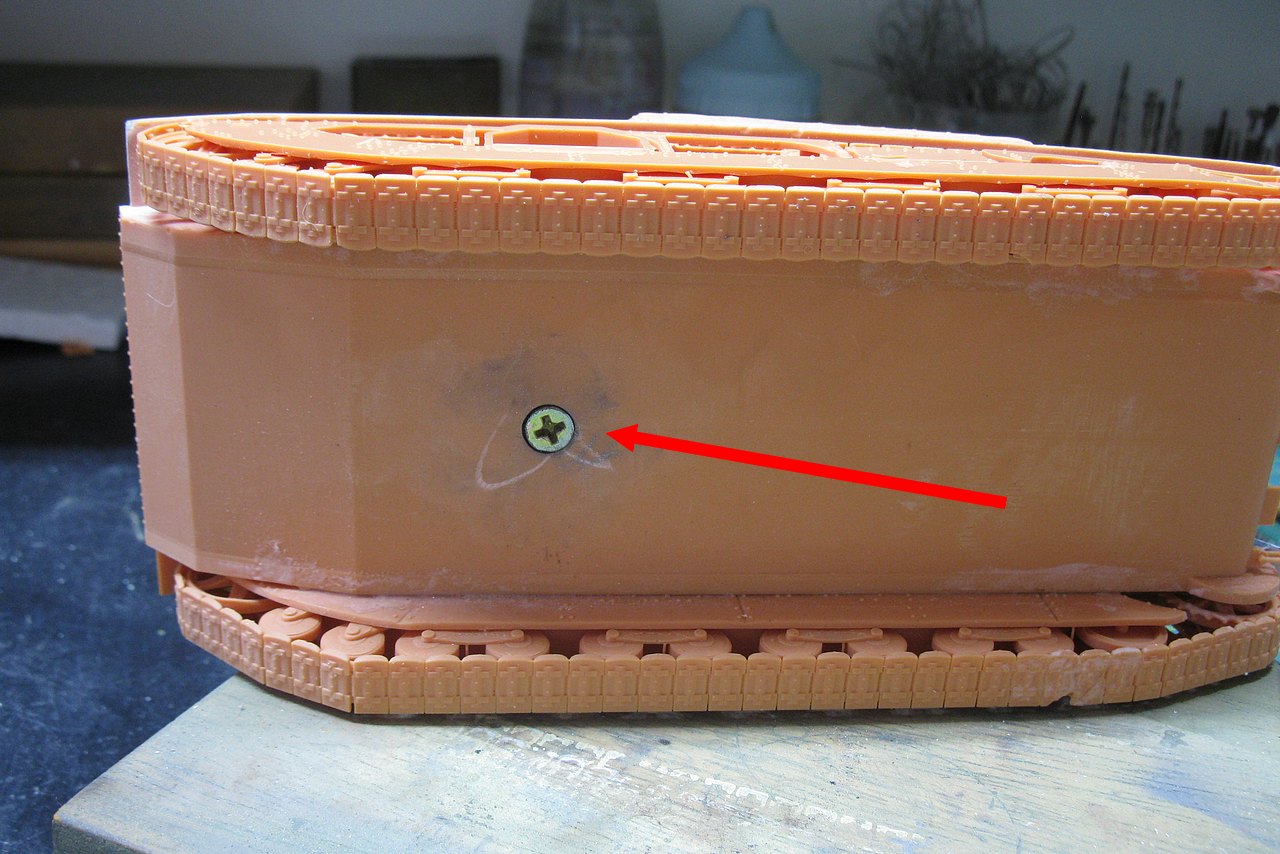 |
| Screw installed, locked in the turret disc, but allowing it to rotate. This portion will be covered with a thin plastic sheet. |
 |
| And the turret rotates, without the risk of falling and breaking!!! |
 |
| Really, things are going smoothly and in advance... |
Now, let's install the 47mm cannon on the main turret. The cannon seems too long to me... the model looks cartoonish... Let's use photos and the blueprint as a reference: the 47mm gun ends on the same line as the front portion of the tank's hull:
 |
| Note that the 47mm cannon ends practically on the same line as the front portion of the tank's hull. |
 |
| Placing a metal template perpendicular to the front portion of the hull: the supplied cannon is much longer (yellow arrow) Compare with the blueprint in the detail.... |
 |
| The cannon barrel, after being cut... |
 |
| The cannon barrel was exactly 41.6 mm!! |
 |
| A comparison between the lengths of the cannons: above is correct; below, in the standard size of the kit |
 |
| The cannon glued to the model, with the metal template being used as a measuring standard: perfect!!! |
 |
| Really, our Flapper girl is very charming!!! Front left view... |
 |
| Front right view... |
Few details left now... Our girl is almost ready... Time to install the ladder, front footboard and tow hooks on the Vickers. The degree of detail used by SS Models printers is impressive. Excellent work, Gentlemen!!!
 |
| Notice the protective cage of these small details: excellent impression... |
Let's install these and a few more details on our Vickers. See below:
 |
| The rear ladder was only present on the right side of the tank (blue arrow). On the left side, nothing (red arrow). I added the support handle at the top of the left rear ladder (yellow arrow) and also the risers at the rear fenders (right and left - green arrows) |
In the model:
 |
| The support handle at the top of the left rear ladder (red arrow) the ladder (yellow arrow) and the riser at the rear fender ( green arrows) |
 |
| I redid the center tow hook with copper wire (green arrow). See also the ladder (red arrow) and the riser at the rear fender (yellow arrow) |
 |
| Left view: notice the absence of the ladder (blue arrow) |
 |
| ...and front details. Again, the kit does not present markings for the installation of these details. Be very careful at this stage!!! |
Now that the construction is almost complete, I can check the measurements of the kit printed by SS Models, based on the technical specifications provided in the literature. Note that as the original measurements are in centimeters, I will keep the transformation of the original measurements to the 1/35 scale in centimeters, as well as the kit measurements, which were obtained by measuring the kit with a metalic ruler and caliper:
 |
| Vickers Medium Mk.III from SS Models Lenght: 19,0 cms I placed two perpendicular pieces of metal, touching the beginning and end of the hull, to obtain the length. |
 |
| Vickers Medium Mk.III from SS Models Widht: 7,8 cms I placed the caliper at the maximum width of the model. Sorry for the image distortions... my camera is very simple.... |
 |
| Vickers Medium Mk.III from SS Models Height: 8,2 cms I placed the caliper at the top of the Commander's cupola and the base of the tracks of the model Sorry for the image distortions... my camera is very simple.... |
Summarizing the measures: In terms of length and height, the kit is a little bigger than it should be, although the discrepancies are not that big, in my opinion... It's not quite a 1/32 kit, but maybe 1/34. Really, the difference is minimal...
 |
| The kit is a little longer and taller than it should be...almost 1/34. |
 |
| And also a little wider than would be correct. But honestly, I think it's within average... My two cents, of course!!! Sorry for the image distortions... my camera is very simple.... |
Congratulations SS Models...
In my opinion, you are approved, but it can be improved!!!!

But, continuing... When studying the real images of the vehicle, I noticed that there are some errors and omissions on the roof of the turret: the hole for the vertical antenna (red in the photo) is poorly positioned (blue in the kit, with the correct position in red) and there is a missing detail on the roof of the turret (green), which appears to me to be an electrical conduit. or something like this. See the details below:
 |
| The hole for the vertical antenna (red in the photo) is poorly positioned (blue in the kit, with the correct position in red). The position of conduit is marked with pencil (green arrow). The wrong hole was plugged with a Plastruct round rod. |
 |
| Corrected and added details - left view green - electrical conduit made with copper wire blue - Wrong antenna hole already sealed and sanded red- new hole for the vertical antenna. |
 |
| The electrical conduit made with copper wire and support handles, made with copper wire right view |
Now, it's time to choose the profile of the vehicle we are going to build. As we saw in the history and as you can see in the period photos, the vehicles underwent several small modifications. But one of the Vickers Medium Mk.III that I particularly liked is this, the MT-9707:
 |
| Vickers Medium Mk III E1 (MT 9707) used as command vehicle Salisbury Plain maneuvers - 12 August, 1934 font: IWM MH 8102 |
 |
| Vickers Medium Tank Mark III E1 (MT 9707) which is being used as his command vehicle Salisbury Plain maneuvers - 12 August, 1934 font:IWM MH 8101 |
My goal is to try to reproduce the details of the vehicle in the photo, but not exactly reproduce the photo. Let's say, the day before or after the photo... who knows??
But enough daydreaming and let's get to work: as the MT-9707 was a command vehicle, it had a "clothesline" antenna around the turret, in addition to the vertical antenna on the roof. I used stainless steel wires (how good it is to be a dentist and have an Orthodontist colleague, in the same Clinic...) bent to size and inserted into the turret, to make the "clothesline" antenna masts. The antenna wire was made with thinner copper wire, bent and glued at the angles with gel superglue. Perfect!!!
 |
| The "clothesline" type antenna, with the copper wire installed and glued. The yellow arrows point to bonding with cyanoacrylate gel. Note the antenna connection made by a black polyester thread, which is inserted into the roof of the turret through a scratch-made plug. front view |
 |
| Left view: the red arrows point to bonding with cyanoacrylate gel and the green arrow to antenna connection made by a black polyester thread. |
 |
| Right view: notice the vertical antenna, made with acupuncture needle (green) and plastic scratch base |
But continuing to build details: time for the steel cables. Note that the Vickers Medium Mk.III uses double steel cables, in duplicate, that is, each tow cable has two steel cables tied by a metal band, forming a single eye. This double cable is installed in the tank with another identical double cable. See the photos below:
 |
| Vickers Medium Mk.III with two double steel cables anchored to the front right tow eye |
We will make the double cables with material from RMG Resin Models, from Portugal. We have already seen this material in the construction of the Matilda I Infantry tank, but this time, I will use a thinner cable (0.6mm in diameter) and use a thin sheet of metal (I will use the metal seal from a can of powdered milk) , as well as gel superglue (methyl cyanoacrylate). But let's go to the "tutorial" on how to make a double steel cable...
 |
| The RMG Resin Models steel cable, in its zip-lock packaging A very good stuff!! |
 |
| I will use the steel cale with 0,6 mm in diameter |
 |
| The manufacturer declares that the total length is 70 cm (700 mm), that is, two rolls of 35 cm. |
The first thing I did was fold one of the segments in half. When I measured, I found that the folded segments were 18 cm, that is, one of the rolls was 36 cm. In the middle bend, with round nose pliers, I made a bend similar to the eye of the steel cable, and I glued (with gel superglue) the segments of the cable just after the eye ( 2 mm only), where the metal sleeve will be installed.
 |
| The RMG Resin Models cable folded, forming an eyelet, with the gel superglue being placed in a 2 mm portion just after this eyelet, to facilitate the installation of the metal band. |
 |
| I will cut two 4mm wide strips of aluminum foil with a scalpel, which will be used as the metal band for our steel cable. |
The idea is to glue the edge of the 4 mm metal sheet just below the eye of the steel cable, wait a few seconds for the superglue to dry and then tightly wrap the metal sheet (with superglue applied to its inner side) onto the cables. , forming the cable retention band.
 |
| The future position of the metal band in the steel cable (yellow square). The metal straps are too long... |
 |
| Location of primary glue application (red line), on the metal strip. It will be glued to the junction between the steel cables, and then wrapped around those same cables, forming the retention band. |
 |
| Thin sheet of metal being glued to the junction between the two cables (green), just below the eyelet. A metal weight keeps the cable well positioned and parallel to each other. Notice that the glued metal strip was cutted almost in half... |
After the band was wrapped and glued below the eyelet, I stretched the double cables and kept them aligned in parallel with weights. At the other end (green arrow), I bent the other eye, so that the meeting between the two ends of the cable is in the region of the future metal retention band. The excess cable without the eyelet bend was cut with precision cutting pliers (green arrow, again). With that, the amendment will disappears... Kojak is a smart guy!!!
 |
| Making the eyelet of the steel cable, at the other end... |
 |
| Detail of the second eyelet, with the wire being cut in the exact portion where the metal band will be installed. Using gel superglue makes the job enormously easier... |
 |
| Preparing the metal band for installation... A minimum amount of superglue for initial gluing (red line) |
 |
| After the initial gluing of the band, I applied more glue to the inner side of the band so that it can be wrapped around the steel cable. |
 |
| The first double steel cable built, held taut by two clothes pins. The cable was 17.5 cm. |
 |
| The trickiest part was making the second cable the same size. To avoid mistakes, I started this second cable through the splice eye, bending the wire according to the clothes pin template. |
After the metal band was installed in the middle fold, I returned to the splice eye, where the excess wire was cut to fit snugly into the base of the eye. Here is the close-up image, where you can see the perfect splice between the two cables, being held in position by a little superglue.
 |
| Preparing the metal band for the eyelet of the amendment. The edge is already glued...all that remains is to apply more glue to the inner side of the band and wrap the band around the cables. |
 |
| Two perfect double cables (yellow arrows)!!! The tow rings (green) are from my scrap box. |
 |
| The detail here was the drilling in one of the tow rings (green) so we could fit a 0.5mm diameter round rod (yellow). That was tense!!! |
And now, install the double steel cables according to the following "recipe":
 |
| The double cables starts in the right front towing ring (red), then pass internally to the left headlight (green), pass through the external side of the right secondary turret (light blue), go up to the upper deck, next to the first support strap (orange) and end up resting on the right rear deck. (dark blue) |
 |
| The right front towing ring... Where it all starts!!! |
 |
| The double cables starts in the right front towing ring, then pass internally to the left headlight. |
 |
| I applied small amounts of gel superglue to the hull (blue arrow), to make it easier for the cables to fit onto the surface. The Portuguese material from RMG Resin Models is very flexible and easy to mold on site... Delicious!!! Notice the front towing ring (red). |
 |
| I replaced the printed resin handles with metal handles made with copper wires, to allow for a firmer and more secure anchoring of my steel cable!! Your material is very good, RMG Resin Models. Congrats!!! |
 |
| And the final appearance of the steel cables, installed on the right side of our medium girl Mk.III. I just loved the final look of the thing, no doubt!!! |
Now, the best part: Colors and markings. As I told you, I really liked the visual appearance of the Vickers Medium Mk.III E1, the MT 9707, as it appeared during the maneuvers at the Salisbury Plains in August, 1934.
 |
| Medium Mk III command vehicle font: IWM MH 8102 |
So, let's create a guide profile for this girl's Colors and Markings! A search for the colors and details of the triangular symbol it carries on the side of the turret revealed very interesting things, which are very well described on the official website of the Royal Tank Regiment (formerly the Royal Tanks Corps). It's really worth a trip there... just follow the link...
 |
| RTR flag: ‘From mud, through blood, to the green fields beyond’. Fear naught!! The Regimental flag is always flown with green uppermost. |
 |
Another Panzerserra markings & colors guide profile The big detail here is to place the symbol with the tank correctly pointing to the left, whatever the direction of the triangular flag on the turret. |
But before the colors, let's go to the primer. I like using white...
 |
| Our pale girl... |
 |
| ...ready for more colorful makeup!!! |
 |
| Uops...wrong picture!!! |
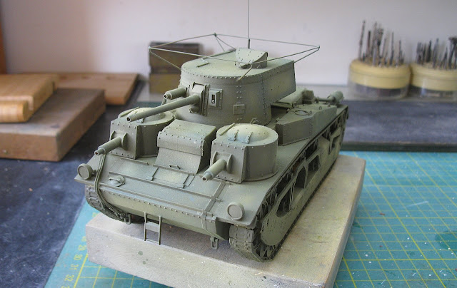 |
| The correct fifty shades of dark green!! 😉 |
 |
| Really, these girls from the interwar period are very glamorous!!! |
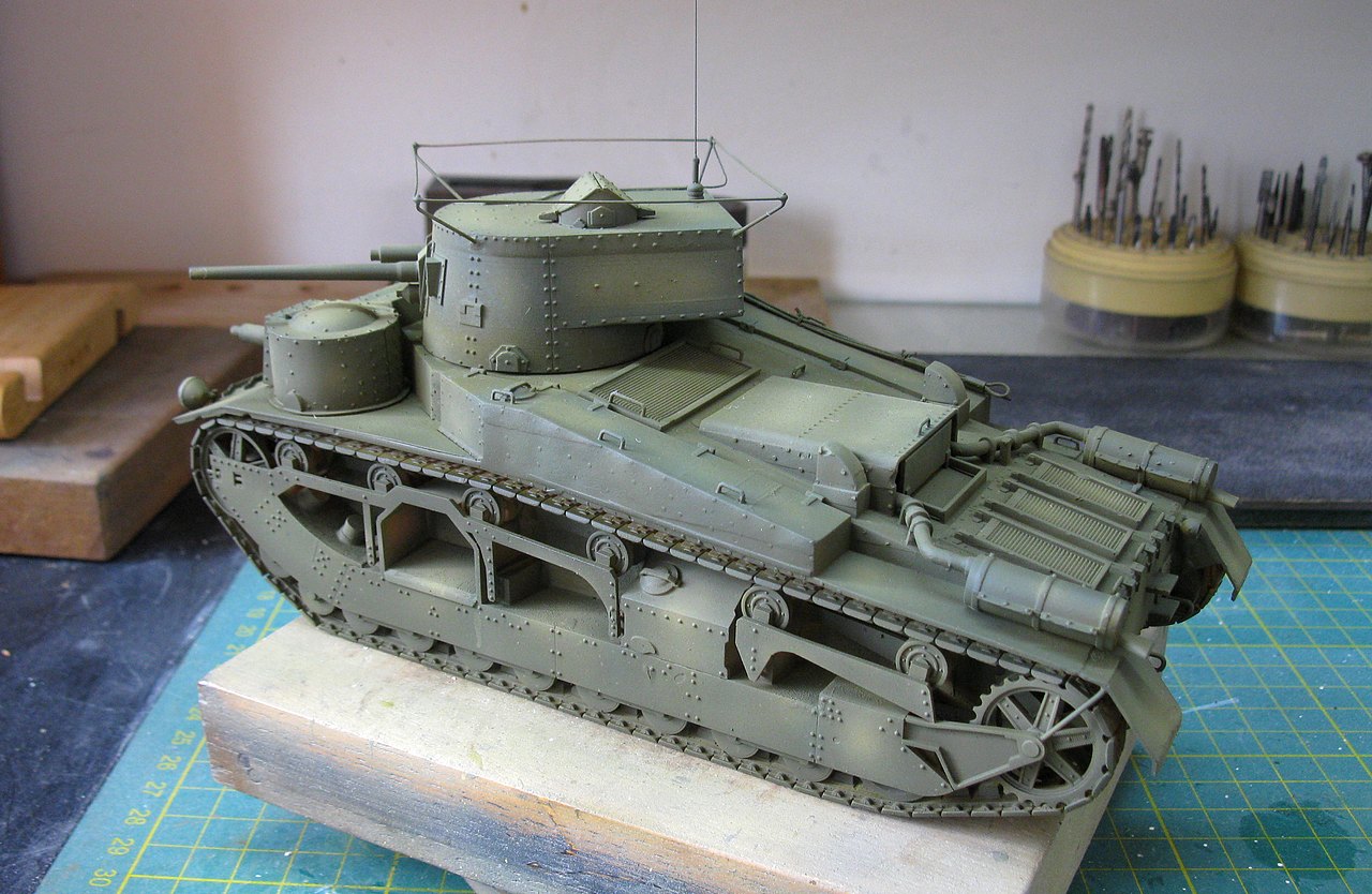 |
| Rear view |
As you already know, I print my decals myself, but as my laser printer does not print white, for the colors to be evident it is necessary to use a white decal the size of the color drawing to serve as a background. But something strange happened this time: the colors printed looked simply horrible. No matter how much I tried to adjust my printer, the result was always this:
 |
| Transparent decals (printed in full color) and the background white decal. The color prints were rotten!!! |
 |
| I applied a discreet layer of Future (Pledge) to avoid silvering and applied the white background decals. Main turret - right side |
 |
| Main turret (left side) with white background decal in position |
 |
| After the white background decal was dry, I applied the transparent decal with the printed colors. Gentlemen, the result was very disappointing: altered colors and no density... left side view |
 |
| The same disappointment on the right side... |
 |
| Applying decals with the vehicle number and the Vickers Limited logo to the vehicle's frontal armor |
 |
| It really is a shame to maintain this marking with such low quality and historical accuracy!!! |
But the old school is good for something: how about applying the correct colors to the decal? The quality of the printing (the central symbol) is good; only the colors are altered and poorly printed... Time to use the good and venerable fine brush, with tons of patience and kilos and kilos of steady hand!!!
 |
| With patience and a fine brush, we will color the colors of the decals. Time to incorporate a holy spirit from Nepal!!! After 10 minutes of sweating and holding the breath (literally), here's the end result. Left side view. |
 |
| ...and right side!! |
 |
| Not bad really, Grasshopper!!! The Tommies are smiling again!!! left view |
 |
| ...and right side!! Royal Tank Corps rules!!! Note the correct positioning of the tank symbol in the center of the flags. |
 |
| Now, let's apply a layer of matte varnish, to seal everything!!! |
 |
| Notice that I painted the exhausts and tracks, preparing for weathering... |
 |
| The vehicle number on the rear of the hull... Next step: weathering...Phew!!! |
 |
| Washes and dry-brush: starting the weathering. Something very discreet, as they were maneuvering machines, just... left front view |
 |
| right front view |
 |
| ...and the rear view. Well, I feel like adding some details here... |
I thought about attaching a chain to the three rear tow hooks. I'm going to use some more of the material I received from Portugal, from RMG Resin Models. Apparently, the Vickers will be a test-bed for these accessories... Although the packaging specifies that it is for use on a German vehicle, we are unorthodox modelers: For the King and for Saint George... 👑👑👑!!
 |
| Metal chain from RMG Resin Models: Place I think about installing (red arrows) 0.2mm thick (great) and 120mm long (that’s it??!!) (blue) |
Here, a constructive criticism for the manufacturer: the appearance of the metal (nickel-plated) and the length, which I found to be too small. Or better said, it is enough, but for just one use, one project... From my point of view, the ideal would be for it to be 150 to 200 mm long. And if it could come with a black finish, it would be perfect...
 |
| Enough for one project only: 120mm (12 cm)... |
But the worst thing is the nickel-plated finish. My solution to this is to simply burn this jewelry-like finish, using a lamp and a hook, so we don't burn our fingers...
 |
| Let's transform a piece of jewelry into a chain... |
 |
| Fire Nation soldiers would be useful now, but the lamp does the same job without many side effects... You can fold the chain into segments, to use the flame very effectively... |
After bringing the chain to a red glow (CAUTION!!), wait for the chain to cool completely before handling it safely. The chain has a dark coppery tone, much better than the original silver...
 |
| Here, the current is already cold, with a dark coppery tone. Ang loved the effect!!! |
 |
| Not satisfied, I applied powdered graphite (with my fingers) to the chain, to simulate a dark metallic effect... |
 |
| And since my fingers were filthy, take advantage and sprinkle black pigment powder over the links... The look is much better than simply painting!! |
And now, a positive point for the RMG Resin Models chain: it is very resistant, as I have already used some chains made from aluminum alloy that simply melt when heated. This one withstood the heat treatment easily, and to open the links (to fit the tank's tow hooks) I had to use fine cutting pliers. When doing this, watch the link carefully, so as not to cut on the wrong side (which destroys the link..)
 |
| Opening a chain link with cutting pliers. Now, insert this open link into the tank's tow hook and compress the link to its normal contour, using heavy (surgical) tweezers or flat needle-nose pliers. |
 |
| And the RMG Resin Models chain in position, in the Vickers medium Mk.III rear hull I liked the material!!! Weel done, RMG Resin Models !!! |
And while I'm adding details, let's put some roll-bags on the upper-deck, only this time from Value Gear Details. First, the inspiration:
 |
| Notice the roll-bags in the upper deck of the tank |
 |
| Selecting material from my Value Gear Details stash. |
 |
| The roll-bags after being painted... |
 |
| ...and glued to the rear of the tank. The girl is getting a little dirty!!! |
And after adding a few more details, I can call this girl ready: with you, Vickers Medium Mk III tank E1 (MT 9707), used as command vehicle in the Salisbury Plains maneuvers, in 12 August, 1934.
 |
| Vickers Medium Mk III tank E1 (MT 9707) - Command vehicle Salisbury Plains maneuvers - England 12 August, 1934. |
 |
| Vickers Medium Mk III tank E1 (MT 9707) left side |
 |
| Vickers Medium Mk III tank E1 (MT 9707) left rear side |
 |
| Vickers Medium Mk III tank E1 (MT 9707) rear right side |
 |
| Vickers Medium Mk III tank E1 (MT 9707) right side |
 |
| Vickers Medium Mk III tank E1 (MT 9707) rear right side |
 |
| Vickers Medium Mk III tank E1 (MT 9707) front right side |
 |
| Vickers Medium Mk III tank E1 (MT 9707) with Kojak!! |
 |
| Vickers Independent A1E1 and Vickers Medium Mk III tank E1 (MT 9707) side by side |
 |
| Vickers Medium Mk III tank E1 (MT 9707) - Command vehicle Salisbury Plains maneuvers - England 12 August, 1934. |
Thank you for following us
and stay with us!!!