
Tankers!!!
The subject of this report is nothing more than the predecessor of a glorious lineage of infantry tanks, but which was born completely out of date for modern fast-moving warfare. Let's get to know the Tank, Infantry , Mark I (A11) Matilda I.
 |
| Modified from IWM O 747 picture |
The Tank, Infantry, Mk I, Matilda I (A11) was a British infantry tank of the Second World War. Despite her low travel speed and a very cramped interior for the crew, the Matilda I achieved some success during the Battle of France in 1940. This was largely due to her heavy armor, which made her virtually immune to standard German anti-tank guns. , of the time.. But equipped with its only machine gun, it was virtually useless, taking into account its offensive capacity, and could not inflict any damage on enemy armor. She was a completely outdated tank before she was even put into active service.
%20%20IWM%20KID%201081.jpg) |
| Infantry tank Mk I Matilda I (A11) font:IWM KID 1081 |
The Battle of France was the only time that Matilda I was employed in an operational capacity. The tank was built extremely economically, as with the winds of War blowing over Europe, the British Government did not want to spend much on a tank that they themselves recognized as temporary. The Matilda I should not be confused with the model that replaced it, the Tank, Infantry Mk II (A12) Matilda II, which inherited the name "Matilda" after the A11 was withdrawn from active service in 1940.
.%20Initial%20production%20type%20%20IWM%20KID%20586.jpg) |
| Infantry Tank Mk II Matilda (A12), who would later be known as "Queen of the Desert" Initial production type font:IWM KID 586 |
At the end of the 1920s, in 1929 more precisely, the Imperial General Staff announced an extensive review of the establishments and organization within the British Army, motivated by recent experiences in the use of mechanization in the Armies, after the end of WWI.
The Infantry was chosen to initiate these changes, with two brigades designated for experimental purposes, each supported by a battalion of "light tanks", which in this case were the completely unsuitable Carden-Loyd Mark VI Machine Gun Carriers.
 |
| Carden-Loyd Mark VI Machine Gun Carrier - 1927. Very, very light tankette... |
War games were played and the exercises indicated what the infantry would expect their tanks to do on the battlefield. The infantry wanted the tanks to be the spearhead of the advance, penetrating the enemy defensive lines, moving slowly forward, allowing the soldiers to follow this advance and to be heavily armored, to be able to absorb enemy fire.
By 1934, all conclusions were pointing to a tank specially developed for this task. The Inspector of the Royal Tank Corps, Major-General Percy C. S. Hobart, after consultation, detailed the two possible alternatives for the future Infantry Tank::
- A small, cheap, not exuberant tank, reasonably well armored and equipped with a machine gun, but with the possibility of being supplied in large quantities on the battlefield, in order to suffocate the enemy defenses by numbers, or...
- A larger, expensive tank, armed with a cannon and having a robust armor, strong enough to withstand enemy field artillery.
 |
(Royal Tank Regiment) * 14th of June 1885 † 19th of February 1957 Nickname: Hobo |
For this task, two men were primarily responsible for developing the Infantry Tank concept: Sir Hugh Jamieson Elles, Master General of Ordnance (M.G.O.), and Major-General A. E. Davidson, as Director of Mechanization (D.o.M.).
 |
| Lt Gen Sir Hugh Jamieson Elles KCB KCMG KCVO DSO ( Master-General of the Ordnance) * 27th of May 1880 † 11th of July 1945 |
 |
(Royal Engineers) * 15th of August 1880 † 29th of January 1962 |
Both had experienced the problems of WWI trench warfare and thinking about future conflicts, neither of them wanted a repeat of the massacre of infantry, the stupid advances of unprotected men on enemy automatic weapons, typical of the First World War.
 |
| Infantry leaving the trench, advancing without cover, across No Man's Land Battle of the Somme - July 1916 font: IWM Q 70165 |
An armored vehicle should be built to assist and protect the infantry. It would have to be well armored, to be able to advance on the enemy trenches, destroying the machine gun nests that claimed so many lives in the previous conflict. This is how the concept of the Infantry Tank was born.
The final decision rested with the Master-General of the Ordnance, General Sir Hugh Jamieson Elles, Commander of the Tank Corps in France during the WWI. Influenced by his own experience, Elles strongly favored the concept of infantry tanks and constrained by a peacetime economy, gave the go-ahead for construction for the smaller, cheaper type, as first priority.
At the end of 1935, in October, the head of tank design at Vickers-Armstrongs Ltd., Sir John Carden, after a meeting at the War Office about the new infantry tank, came out with the outline of a proposal for the construction of a small two-man tank, armed with a single machine gun, but two conditions:
- The vehicle had to be ready within six months.
- The vehicle had to be cheap.
 |
| Sir John Valentine Carden, 6th Baronet , MBE * 6th of February 1892 † 10th of December 1935 |
 |
| John Carden’s original sketch of the A.11 Notice the Vickers suspension, the two men crew and the main armament of the tank 03-10-1935 font: Fletcher, D. (1991). Mechanised Force. HMSO, UK |
 |
| A11E1 prototype T1724 (first version) Infantry Tank Mk I Matilda (A11). right front view Notice the toothed front idler wheel and very crude details in the hull. Notice the driver's hatch fully open, interfering with MG. |
The prototype tank was small, with a low and narrow hull, with a small cylindrical cast steel turret, containing a Vickers machine gun, amidships. This turret was quite cramped for the Commander, and the conditions of the driver, located in front of him in an equally cramped compartment, was not much better. Another unpleasant detail was that the driver's hatch interfered with the machine gun in the turret, because when the gun was pointing forward, the hatch would only open with the gun at maximum elevation. The first version of the prototype featured the toothed idler wheel, but this was soon modified in the same prototype, as a measure to help combat the accentuated wear of the tracks. (see pic above).
 |
| A11E1 prototype T1724 (CMN 880) Infantry Tank Mk I Matilda (A11). front top right view Note the lip on the upper front portion of the turret. (typical of the prototype) and the turret's roof has removed. |
 |
| A11E1 prototype T1724 (CMN 880) Infantry Tank Mk I Matilda (A11). Trials on uneven ground. Note the presence of rear fenders and a tool box just behind the idler wheel. The turret's roof has not yet been installed. |
.%20A11E1%20prototype%20%20IWM%20KID%20158.jpg) |
| The same A11E1 prototype T1724 (improved version) Infantry Tank Mk I Matilda (A11). Notice the toothless idler wheel and complete roof turret font:IWM KID 158 |
 |
| A11E1 prototype T1724 (CMN 880) Infantry Tank Mk I Matilda (A11). front right view Note the turret fully assembled font:IWM KID 68 |
 |
| A11E1 prototype T1724 (CMN 880) Infantry Tank Mk I Matilda (A11). rear left view font: IWM STT 2254 |
Designed for quick delivery as well as low cost, the A11 tank used many stock parts from other vehicles: a Ford V8, 3.6 Litre, petrol, Model 79, with 70 hp, a Fordson gearbox, a steering mechanism similar to the one used in Vickers light tanks Mk VIs, driving the rear sprockets. All these mechanical parts were installed in the rear portion of the tank.
 |
| Matilda I (A11) engine |
 |
| Matilda I (A11) engine bay. Drawings kindly provided by our friend Stephen Tegner. Thank you, my friend!!! |
See, below, the engine bay of the Matilda I. The left cover engine is lifted, in the picture. In the diagram below, identify in the lids (checkered in red) the two of the three hinges of the cover (red circles), the the left handle of the transmission cover lid (blue circle) and the first anterior hinge of the left hull edge (in green). The engine practically fills the entire space. Notice the radiator and fan, just before the fire wall. The angle of view is from posterior to anterior (olive green arrow):
 |
| The Ford V8, 3.6 Litre, petrol engine,installed in the tank rear hull. Identify the details highlighted in the drawing (left) with their counterparts in the photo, in the right. |
The suspension train was adapted from the Vickers Mk IV Dragon artillery tractor, that was based on the Vickers 6-Ton Tank. The suspension design is from John Carden.
 |
| Suspension element designed by John Carden and used widely on Vickers light tanks |
 |
| Vickers 6 ton Tank twin turreted Notice the bogies of suspension |
 |
| Dragon Mark IV Vickers artillery gun tractor - side view Notice the suspension bogies, same of the Matilda I font:IWM MH 8408 |
 |
| Dragon Mark IV Vickers artillery gun tractor Notice the suspension bogies and tracks, same of the Matilda I font:IWM MH 8407 |
The suspension consisted of two stations on each side, each consisting of four pairs of rollers acting against a quarter of elliptical springs on a central support that included a return roller. The prototype also featured toothed idler wheels and medium-pitch manganese steel tracks. Both the wheels and suspension units were completely exposed.

 |
| Relationship between suspension elements and tank hull |
 |
| The suspension of a production Matilda I being extensively tested in a proving ground England - early1939 |
Although the prototype was constructed only of mild steel, the tank featured an excellent 60mm at the front and in fact relied on the rigidity of its thick plate for structural integrity, there being no internal structure to support the armor.
 |
| The 60mm thick frontal armor plate (production tank) |
The tank weighed around 11 tons and had a maximum speed of around 13 km/h, which was considered acceptable for keep pace with the infantry.
 |
Matildas I - Tank Infantry Mk I (A11) from Royal Tank Regiment operate with infantry of 2nd Battalion North Staffordshire Regiment during exercises near Hebuterne, France 11 January 1940 - (Drôle de Guerre). font: IWM F 2105 |
The tests revealed the usual series of failures for a new design, the worst of which was a constant failure of the track pins. This was improved early on by replacing the toothed idler wheels with toothless ones and then eliminated in April 1937, when the rear suspension unit on each side was lowered, which increased the sprocket's ground clearance by 130mm.
 |
| Matildas I from 8th RTR being taken care of... The eternal maintenance work with the tracks |
Another defect detected was the premature wear of the two rear sets of rubber-tyred road rollers on each side were replaced by all-steel ones.
 |
| Matilda I (A11) - suspension components Notice the road rollers in rubber and steel. |
As already mentioned, the driver's position was very cramped, with poor ergonomics, forcing the crew member to operate in a very uncomfortable position. This inadequacy was detected in the prototype, but as this deficiency came from the hull design, this defect could not be corrected in production tanks.

Drivers also complained about the forward vision devices, but these issues were postponed until improvements to production machines, although in fact little was done until the appearance of the second batch.
 |
| Matilda I (A11) DEOCH tank driver, in his cramped battle station, with the very tight and dangerous front vision slit. 4th Royal Tank Regiment - France - (Drôle de Guerre). -12 January 1940. font: IWM F 2141 |
The most significant difference between the prototype and production tanks involved the turret, which lost its prominent lip and now featured a two-segment hatch and Commander periscope.
 |
| The proeminent lip in the prototype tank and its absence in the production tank (red) Notice the Commander's periscope (blue) |
The cilindric cast turret was fitted with a single heavy machine gun, either a .303 (7.7 mm) calibre Vickers machine gun or the larger (12.7 mm) Vickers .50 machine gun. The lack of a gun with anti-tank capability severely limited its utility on the battlefield.
 |
| Vickers machine guns |
 |
| Matilda I (A11) - turret - external view |
 |
| Matilda I (A11) - turret - internal arrangements |
Besides operating the machine gun, the Commander had to direct the driver and operate the radio. There being no room in the turret for the radio, it was placed in the right side of the hull: the Commander had to duck down inside and lie almost prone to operate it.
 |
| Internal stowage of the right plate of Matilda I Notice the wireless location |
Production tanks also featured return rollers that were not directly attached to the suspension struts, while the tracks were located further away from the hull than on the prototype.
 |
| Some differences between prototype and production vehicles. |
The first batch production of 60 tanks had headlights mounted high on the hull, just forward of the turret. The remaining 79 had them installed lower, near the nose, due to changes required when the Fowler coulter plough (mine plow) was adopted. Most A11s also had two storage lockers, arranged pannier fashion either side of the nose.

 |
| Matilda I with Fowler coulter plough left side view |
 |
| Matilda I with Fowler coulter plough front left side view |
 |
| Matilda I with Fowler coulter plough close-up front left side view |

Although there is no doubt that these little tanks were designed to be used against specific objectives in large numbers, for in practice they were little more than mechanised infantry machine guns, they were never ordered in quantity.
The first order of 60 Matilda tanks was placed in April 1937, followed by an order for a further 60 ten days later. This quantity was almost enough to equip two battalions. This was not due to excessive savings but a change in policy, and the final order to Vickers for the Mark I Infantry Tank, placed in January 1939, totaled just 19 machines. The reason was that, with war now inevitable, it had been decided to produce a cannon-armed Infantry tank after all, and create up to six army tank battalions to operate them. The new tank was to be known as the Matilda Senior or Tank, Infantry Mk II (A12) Matilda II.
 |
| Infantry tank Mk.II (A12), Matilda II. font:IWM MH 9264 |
The tank remained in production until August 1940, with a total of 140 produced, including the prototype. In summary, the Matilda I was born obsolete both in its design and for the tactical purpose for which it was intended.
The first models were delivered in 1938 to the 1st Army Tank Brigade. There were 65 available in September 1939 when the war started.
 |
A group of Royal Tank Regiment soldiers photographed on an Infantry Tank Mark I, A11 Matilda. Sptember, 1939. font: Tank Museum Bovington |
 |
| Two brand new Matilda Is advancing in open field |
Matilda I tanks equipped the 4th Battalion and 7th Battalion of the Royal Tank Regiment (RTR). In September 1939, upon the outbreak of the Second World War, the 4th RTR deployed to France with the British Expeditionary Force.
| Matilda Mk I tanks of 4th Royal Tank Regiment being transported by train from Cherbourg to Amiens. France - 28 September 1939 font: IWM O-577 |
| Matilda Mk I tanks of 4th Royal Tank Regiment being transported by train from Cherbourg to Amiens. France - 28 September 1939 font: IWM O-576 |
 |
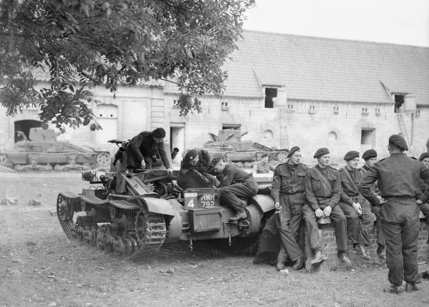
| Crews of 4th Royal Tank Regiment work on their Matilda Mk I tanks beside farm buildings in Acq, Pas-de-Calais France - 19 October 1939 font: IWM O-747 |
 |
| Color profile of the tank in the picture (foreground) above |
 |
| Matilda Mk I tanks and crews of 4th Royal Tank Regiment in a farmyard at Acq, Pas-de-Calais France - 19 October 1939 font: IWM O-742 |
 |
| A Matilda Mk I tank camouflaged beneath shrimp nets Acq, Pas-de-Calais - France - November 1939 font: IWM O-386 |
 |
| Two Matilda Is supporting a small group of infantry from British Expeditionary Force on maneuvers, huffing and puffing in a snowy field. Somewhere in France - winter of 1939-1940. |
 |
| Matilda Is from Royal Tank Regiment, operate with infantry of 2nd Battalion North Staffordshire Regiment during an exercise. Hebuterne, France - 11 January 1940. |
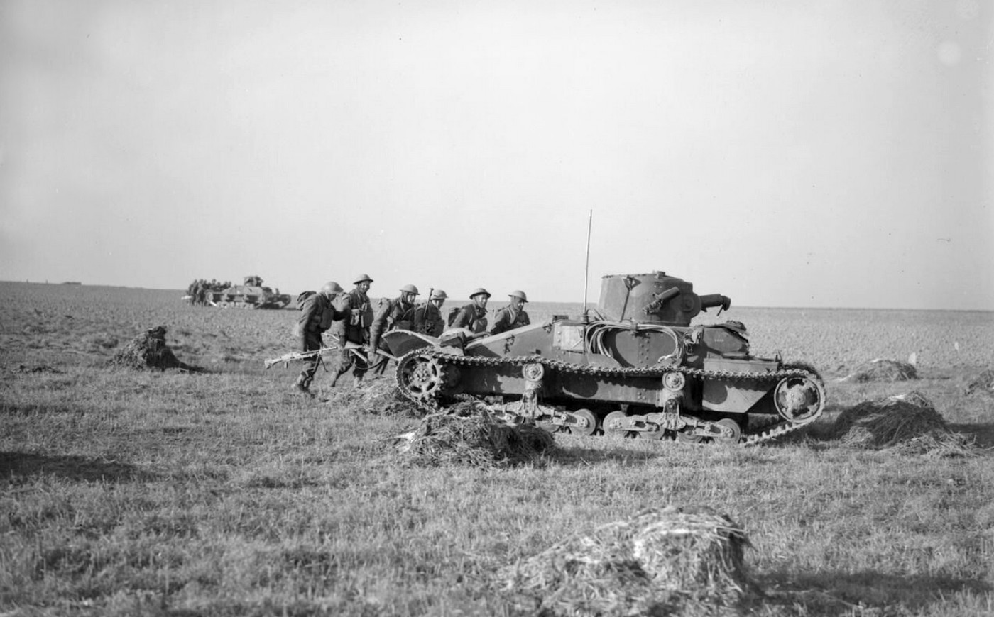 |
| Matilda Is from Royal Tank Regiment, operate with infantry of 2nd Battalion North Staffordshire Regiment during an exercise. Hebuterne, France - 11 January 1940. font: IWM F-2105 |
 |
| Matilda Mk.I tanks from 4th Royal Tank Regiment and infantry of the Coldstream Guards, waiting orders. France - 12 January 1940 font: IWM F-2140 |
 |
| Close-up of the driver of a 4th Royal Tank Regiment Matilda I tank, named 'DEOCH' France - 12 January 1940. Notice that tank displays the vision slit of the 1st batch and the headlights of the 2nd batch of production. font: IWM F 2141 |
They were joined at the start of May 1940 by 7th RTR and together formed the 1st Army Tank Brigade. Apart from light tanks assigned to the various British infantry divisions, this was the only British armoured force on the Continent at the start of the Battle of France on 10 May 1940.
The 58 Matilda Is and 16 Matilda IIs spearheaded the counter-attack in the Battle of Arras on 21 May, temporarily discomfiting the 7th Panzer Division under Erwin Rommel.
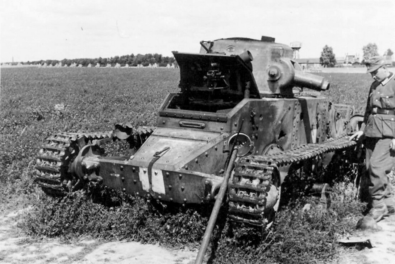 |
| Matilda I destroyed, being inspected by a German soldier. Note at least one lateral solid AP penetration 1st Army Tank Brigade - Arras, France - 1940 |
 |
| Matilda I from 7th RTR abandoned, being inspected by a German soldier 1st Army Tank Brigade - Arras, France - 1940 |
 |
| Matilda I GLENORG destroyed (and cannibalized) in France - May, 1940 |
The heavy armour of both types of British tank proved to be resistant to the standard German 3,7 cm PaK 36 anti-tank gun and the attack was only halted by a gun line hastily formed from 10,5 cm leFH 18 field howitzers and 8,8 cm FlaK 36 anti-aircraft guns, personally directed by Rommel. On the following day, only 26 Matilda Is and two Matilda II tanks were still serviceable.
 |
| 3.7cm Pak 35/36 anti-ank gun Dragon Models box art (#6152) |
 |
| 10.5 cm leFH 18 field howitzer Dragon Models box art (#6795) |
 |
| 8,8 cm FlaK 36 anti-aircraft gun Dragon Models box art (#6260) |
On 23 May, tanks from 7 RTR fought a rearguard action at Souchez before joining the general withdrawal towards Dunkirk. The surviving tanks of both battalions were formed into a composite unit, which fought another counter-attack at La Bassée. Only two tanks reached Dunkirk in the closing stages of Operation Dynamo.
 |
| British troops lined up on the beach awaiting evacuation Dunkirk, France - 1940 |
 |
| Two Matilda Mk. Is from the 1st Tank Brigade covering the retreat of the English infantry to Dunkirk. France - 1940 |
Further south in France, five Matilda Is and a few other tanks which had been in various depots or had arrived as late reinforcements, formed the Divisional Tank Company of the Beauman Division, an improvised formation which had been hastily put together to defend the British logistic bases at Rouen and Dieppe. On 8 June, the tanks supported the force, which was mainly infantry, in their unsuccessful defence of the rivers Andelle and Béthune.
The division was subsequently evacuated from Cherbourg during Operation Aerial; although 22 tanks of various types were brought back during these evacuations, there were no infantry tanks among them.
After most of the deployed Matilda I tanks were abandoned in France, the 77 Matilda Is left in the United Kingdom were withdrawn for training purposes.
A Matilda I was selected by the German Army for evaluation and it was destroyed in the process. Some recent evidence suggests that Matilda I's captured by the Germans may have seen use as internal security vehicles, probably in Poland, under German designation of Infanterie Panzerkampfwagen Mk I 747(e).
 |
| Matildas I and II, along with French tanks, being inspected by the Germans, in an armor junkyard. Somewhere in France - late, 1940. |
 |
| An inglorious end for a captured Matilda I (T5574): being used as support for a clothesline. Somewhere in France - 1940. |
The 1st Army Tank Brigade had 77 Matilda Is by May 1940. Went with 4th and 7th Royal Tank Regiment, and 1st Army Tank Brigade to France in 1940 and took part in battle of Arras. At the Battle of Arras there were 58 Matilda Is. After Dunkirk, the remaining vehicles used for training.
| Matilda I tank of the Royal Tank Regiment,1st Armoured Division, being transported aboard a flatbed railway wagon. Great Britain - 22 July 1940. font:IWM H 2417 |
 |
| Matilda I of the 10th Polish Armoured Cavalry brigade in training - Somewhere in Britain - 1941. |
Survivors:
Three surviving Matilda I tanks are preserved at Bovington - The Tank Museum in the United Kingdom. One (HMH 802, identified as "possibly T3447" is in running condition; it was recovered from Otterburn gunnery range and restored to running condition, although it is powered by an inauthentic engine and gearbox.
The second vehicle was built in March 1940 and restored to running condition in the 1980s. It is painted to represent T8106 (PMX 466) a tank of the 4th Royal Tank Regiment in France in May 1940.
A third Matilda I is a severely damaged wreck that was used as a gunnery range target, and can be found to the north of the Vehicle Conservation Centre.
 |
| Two of the surviving Matilda I at Bovington Tank Museum exhibit the characteristics of the 1st.and the 2nd. batch production. Notice also the different shape and position of the two storage lockers, on each side of the tank nose. |
 |
| Matilda I hull and turret, used as gunnery range target. Bovington Tank Museum |
Specs:
%20specs.jpg)
| Tank, Infantry, Mk I - Matilda I (A11) | |
|---|---|
| Type | Infantry tank |
| Place of origin | United Kingdom |
| Service history | |
| In service | 1938–1940 |
| Production history | |
| Designer | Sir John Carden, Vickers-Armstrongs |
| Designed | 1935 |
| Manufacturer | Vickers-Armstrongs |
| Produced | 1937–1940 |
| No. built Serial numbers | 140 T 3433 - T 3492; T 5551 - T 5610; T 8101 - T 8119. |
| Specifications | |
| Mass | 11 t. |
| Length | 4.85 m |
| Width | 2.28 m |
| Height Ground clearance | 1.86 m 0,38 m |
| Crew | 2 (commander gunner, driver) |
| Armour | 10 - 65 mm |
Main armament | Vickers .303 or Vickers .50 mgun 4.000 rounds |
Secondary armament Radio | none Wireless set no.9 |
| Engine | 3.6 Litre V8 Ford Model 79 petrol 70 hp @ 3500 rpm (52 kW) |
| Power/weight | 6.36 hp/ton |
| Suspension Fuel capacity | Sprung bogie 190 liters |
Operational range Fording depth Trench crossing Vertical obstacle | 130 km 0,76 m 2,15 m 0,76 m |
| Maximum speed | 12.87 km/h on road 9 km/h off road |
The kit:
I choose the full resin kit (#K067) Matilda Mk.I British Infantry Tank, from Accurate Armour. It is a classical kit and proven to be well cast and very reliable
 |
| Accurate Armour K067 kit box art |
All parts come in a sturdy cardboard box, with subassemblies packed in zip-lock plastic. The good news is the presence of photo-etched parts and, a rarity in resin kits, an excellent decal sheet....
 |
| Kojak with Accurate´s Matilda I resin kit parts. |
Worrying news are the tracks, in complete strips... Hmmm... this is really worrying... even more so as Matilda I's tracks are characteristically a little loose...
 |
| Matilda I's tracks, totally exposed and a little loose.... |
But that is a future problem. Like Jack the Ripper, let's do our work in parts.... Starting at the beginning:
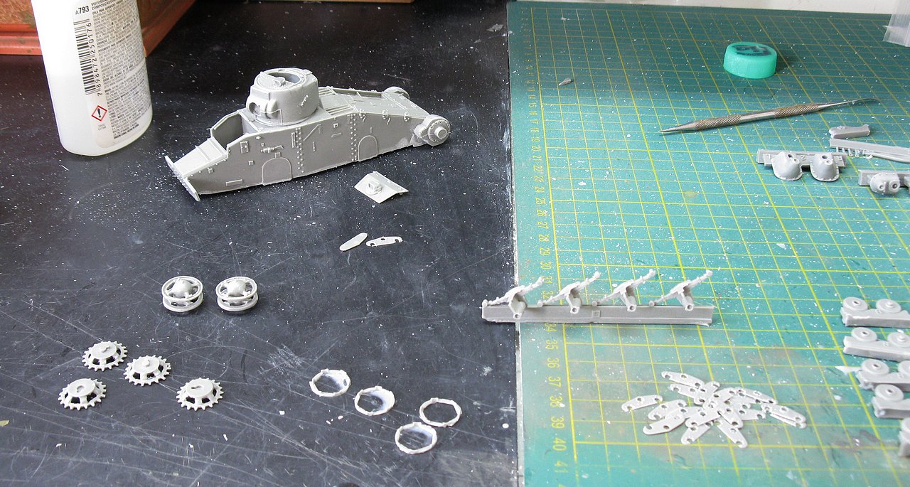 |
| Starting cleaning the parts... |
 |
| Little parts in detail... |
 |
| Lots of wheels, man!!! |
 |
| A little part from de bogies broken, without any extra parts... Hmmm...what an ugly economy, Mrs. Accurate!! |
 |
| Plastruct to the rescue!!! |
 |
| Starting the construction of the articulated arms of the suspension bogies... Lots of care and attention, using super glue... No way back!!! No margin for error!!! |
Time to build the suspensions bogies supports. Here, alignment is fundamental!!! My tip for these delicate collages: a micro-drop of super glue to check the alignment... If everything is correct, "sew" the piece with more super glue, applying the liquid with a thin wire on the periphery of the piece. Capillarity will take care of the rest...
 |
| The suspension bogie supports. Perfect!!! |
 |
| Our girl's little paws are starting to grow.... |
 |
| Installing the suspension arms: here, alignment is ALSO essential!!! |
 |
| Metal parts framing the entire assembly and applying a little weight to the vehicle... |
 |
| These small precautions prevent the suspension from being "born" warped... |
 |
| And voiláa: everything aligned on the 3 axes!!! left view |
 |
| Perfectly aligned suspension arms. Right side view |
 |
| Testing the fit of the scratch made with Plastruct of the broken suspension piece. So far so good!!! |
 |
| Bogies built and installed. Be very careful with the position of the rear bogie, with its all-metal wheels located further back... The track strips are already clean, awaiting installation... left view |
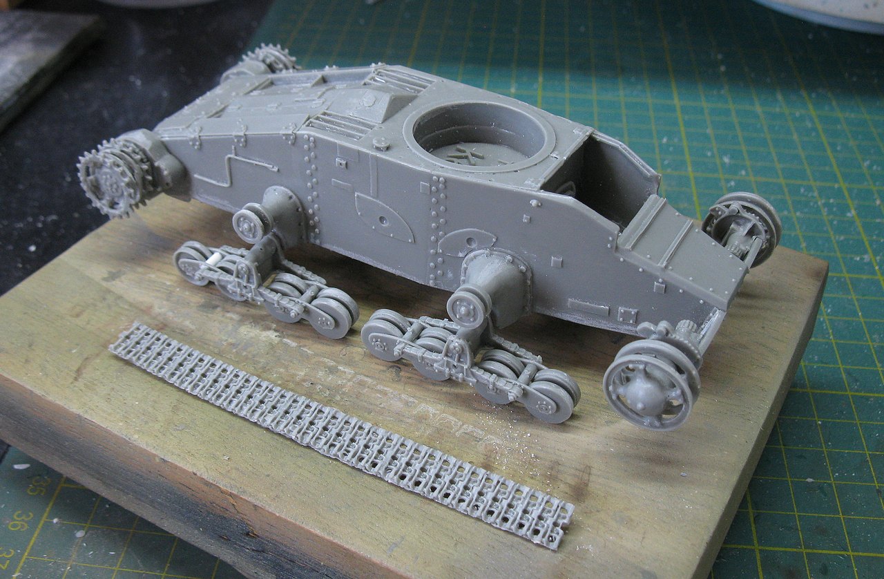 |
| Bogies built and installed. Be very careful with the position of the rear bogie, with its all-metal wheels located further back... The track strips are already clean, awaiting installation... right view |
Starting to install the resin tracks, I decided to use a new technique: hot air gun!! I heated the track segments very carefully with a heat gun and, wonder of wonders: the segments are softened enough for you to be able to shape the tracks on the wheels and return wheels...
 |
| A cheap and generic hot air gun |
Sorry I didn't take photos of the stages (I was a little confused with the heat gun and didn't want to run the risk of "melting" the tracks...), but the technique is excellent!!!
 |
| Notice the track on the return rollers, with the fit simulating the weight of the tracks |
 |
| A slightly more distant view... |
 |
| Tracks on the left side with complete installation. Right side with the upper portion already installed... |
 |
| Tracks on the right side with complete installation. |
When shooting these photos, I almost dropped the turret. Hell, this is worrying. I'm going to make a system with a screw to retain the turret in the correct position, allowing it to move but preventing it from falling. I will use a long Phillips screw, which will be installed through the tank hull. Then, I will close the access with a thin plastic plate.
 |
| The screw in positio (yellow arrow). Notice the recess I made in the hull to "hide" the screw head. This recess will be covered by a thin sheet of plasticard. |
 |
| The tirret is safe now. I installed the machine gun in its position. The rotation is 360°. |
 |
| This little girl is so cute!!! |
 |
| The turret screw access panel is in position... |
 |
Two Brit girls under construction: Vickers Medium Mk.III in the background. |
After a long, long time, we're going to resume building Matilda I, because I haven't finished this girl yet!! I closed the driver's hatch...after all, Tommy is a very shy guy... The kit has some casting defects, which will be corrected as construction progresses.
 |
| Driver's hatch closed... you can never be too careful!!! left view |
 |
| Driver's hatch closed... right view |
Installing the vent blank plate in place, as well as the radio antenna support. This constructive stage is quite boring. You can't be too careful. First, the locks of the vent blank plate (in PE)
 |
| Note the semicircular steel rope holders, on the right side of the hull, in resin. |
 |
| Gluing the stowage bins in the nose of the Matilda I |
 |
| The vent blank plate in position!! |
Now, I'm going to use a material that I got at the end of the year: a steel rope made with copper wires, from RMG Resin Models, from Portugal. The cables come in different diameters and are pre-painted, which makes things a lot easier. This will be the first time I use material from this Company. The cables come in diameters of 1.2mm, 1.0mm, 0.8mm and 0.6mm. All with a length of 700mm (in two 350mm rolls).
 |
| Steel ropes from RMG Resin Models (Portugal). The cables come packaged in practical zip-lock bags. |
Due to the size of the tank, my choice was the 0.8mm diameter cable. I didn't purchase the resin terminals for the cables, but I'm going to make these eyelets myself, because on the original tank model, the cable eyes were simple.

 |
| The chosen steel cable and its future position... |
 |
| The cables come packaged in practical zip-lock bags, with two 35 cm long rolls each. |
The first thing to do is to make a template that will allow me to work with the steel cable without any wrong bends or concerns... I made a cardboard template, slightly smaller than the area of the steel cable, so I could make my own wire rope jig. Follow me...
 |
| Cardboard template, slightly smaller than the area of the steel cable, in position. |
 |
| Using the cardboard template to cut out the Styrofoam template (where I will wrap the steel cable). Template format drawn on Styrofoam |
 |
| Cutting the Styrofoam into the desired shape |
Before using the Styrofoam template (which is fragile) I will make the eyes on the steel cable, bending the braided copper wire to the desired size, gluing the steel cable with gel superglue and tying it with polyamide thread (no hairy wires here...), to form the eyelet. Simple and effective.
 |
| Making the eylet in the steel cable... |
The steel cable being glued makes it easier to apply the black polyamide thread (see above). A knot, a micro-drop of superglue, cut off the excess black thread, wrap the thread around the steel cable (previously "greased" with gel superglue) and a perfect homemade steel cable eye!!!
 |
| Initial phase of winding the steel cable eye. |
 |
| The correct length for what we want is 20 cms. Here's the steel cable stretched, with the two eyes ready, on the bench! |
Now, let's make 4 turns of the steel cable in our Styrofoam template. The use of superglue is not to glue the cable to the Styrofoam, but the layers together. I applied it to the lower portions, as they will be "hidden" by the semi-circular rack of the hull. You must leave the eyelets up... see the images...
 |
| The steel cable wrapped around our Styrofoam jig. Two micro-drops of superglue in the corners of the steel cable |
 |
| The RMG Resin Models material is very flexible and stable... Loving it!!! Cutting the Styrofoam jig for removing the steel cable roll |
 |
| And the steel cable roll ready to be installed. Chuck Norris approves!!! Congrats, RMG Resin Models!! That's what I call efficient simplicity!!! |
 |
| And the steel cable in position!!! |
 |
| All that was missing was the metal clip (from the kit itself) to keep everything in its place!! I think I'll use more of this Portuguese material, without a doubt!! |
Continuing with the assembly... I came across two pieces (24) whose correct position was actually very confusing in the instruction manual (which is terrible... have I said that before??). There are two pieces of reinforcement for the frontal armor. Here is the image of the instructions:
 |
| The horizontal positioning of these pieces is a mystery... |
 |
| But thanks to Stephen Tegner's drawings... |
 |
| ...and photos of Bovington Tank Museum Notice the green arrow...the part pointed by red arrow (E21) will be installed soon! |
 |
| Goodbye doubts!!! Parts 24 installed!! The screw will receive an extra-thin plastic panel to cover it. |
 |
| More and more details being added to the project... The kit is accompanied by a great PE sheet Note the E21 pieces glued into position |
 |
| Handles on the front toolboxes made with copper wires... Horn installed on the left headlight arm |
 |
| Along with the rear fenders, I added acrylic resin to form a mud texture. Census number and AoS plates in position at the rear of the hull. |
 |
| Making the tension spring for the antenna base, on the right side of the tank. Very thin copper wire wrapped around an acupuncture needle to make the spring (blue arrow), which will be installed in the position indicated by the red arrows |
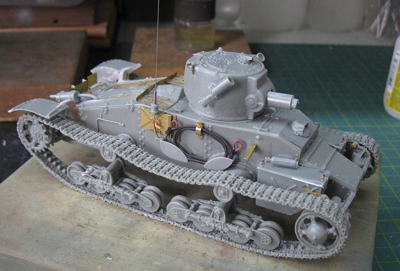 |
| Ready...Tensor spring installed!! Note the smoke grenade launchers on the sides of the turret |
 |
| Details and tools installed on the left side of the hull |
 |
| I discovered that one of the right headlight support arms is broken and missing (blue arrow)... ouch!! Glad the others are ok.(green) |
 |
| Notice the rear view mirror and the AoS sign, in front of the girl's hull... |
 |
| But enough talk: let's make a new arm for the headlight... Plastruct round rod in position... |
 |
| Two segments of different thicknesses of Plastruct were perfect... |
And now let's check the measurements of this old Accurate Armor kit, using the following methodology: measurements quoted in centimeters, showing in sequence the real measurements (1/1), their conversion to model scale (1/35) and the measurements obtained from the model (kit), using rulers and calipers. See the pics below:
 |
| For the length, we will use two limiters and a metal ruler... |
 |
| For width, a caliper installed across the widest width of the vehicle... |
 |
| And for height, a caliper installed at the highest height, from the turret to the base of the vehicle's track. |
And with you, the result: Simply impressive!!!
 |
| Accurate's acuity is incredible!!! (Sorry, I couldn't resist the pun...) Measurements very close to perfection!!! |
 |
| Taking into account the age of the kit, how the model master was executed and the contractions of the material used, the results are fantastic. |
Here's my reaction when checking the measurements...
 |
| Accurate Armour, you rocks!!! |
 |
| And the Matilda I is practically ready to paint... What a wonderful project!!! Front left view |
 |
| Front right view |
 |
| Rear left view |
 |
| Rear right view |
Now, markings and colors!! My choice for this project is this Matilda I with a very powerful name: DREADNOUGHT!!!
 |
| Crews of 4th Royal Tank Regiment work on their Matilda Mk I tanks beside farm buildings in Acq, Pas-de-Calais. Notice the DREADNOUGHT in foreground France - 19 October 1939 font: IWM O-747 |
 |
| Panzerserra markings and colors guide profile Notice the "Chinese eye" in the sides of turret |
Interesting details in these 4th RTR vehicles are the presence of the "Chinese Eyes" (if you want to know more about this interesting story, download the paper in PDF by clicking on this link) and the paint stains that showed a possible chemical attack with gas, on the cupola of the commander and in the front portion of the MatildaI's upper deck.
 |
| An abandoned Matilda I in France. Notice the paint stains showing gases on the commander's hatch and on the upper front deck of the tank (orange arrows) |
Let's start the aesthetic work with the application of the primer.
 |
| The Matilda I in light gray primer... |
I chose dark green and medium green as the colors for this Matilda's camouflage, although some sources mention khaki brown and green. The color base is the dark green, which was applied with an airbrush, with small tonal variations. Afte the base paint dries, I masked the dark green with modeling clay Play-Doh, as a masking agent.
 |
| The Matilda with color base (dark green) applied. After the base paint dries, I used modeling clay as a masking agent. - left view |
 |
| Right view. Next step: medium green color over all... |
 |
| Medium green (and its tonal variations) applied to the vehicle. |
 |
| After removing the clay mask, the camouflage becomes evident Right side view |
 |
| Left side view |
 |
| Painting other details on the tank with a brush... left view |
 |
| Painting other details on the tank with a brush... right view |
 |
| Painting other details on the tank with a brush... rear view |
The Accurate kit comes with an excellent decal sheet, for building various vehicle options, but strangely, the sheet does not contain the paint stains that indicate a gas attack. I'm going to make these spots with a brush, using dark yellow and green, to achieve the desired color.
 |
| My anti-gas paint recipe: Vallejo Pastel green (70885) and Japan Uniform WWII (70.923) |
 |
| Decals in position: DREADNOUGHT was born!!! |
 |
| Matilda I DREADNOUGHT left side view |
 |
| Matilda I DREADNOUGHT right front side view |
 |
| Matilda I DREADNOUGHT right side view |
 |
| Matilda I DREADNOUGHT rear left side view |
 |
| Washes and weathering... left front view |
 |
| Washes and weathering... right front view |
 |
| Washes and weathering... rear left view |
I will add a detail to the upper rear deck of the tank: Value Gear Details.
 |
| Selecting a resin roll bags from Value Gear Details. |
 |
| ...and roll bags painted and glued in place!! |
That's it... our little but brave warrior is ready!! With you, Matilda I, Tank Infantry, Mk I - (A11) DREADNOUGHT with 4th Royal Tank Regiment in Acq, Pas-de-Calais, France, in 19 October 1939.
 |
| Matilda I, Tank Infantry, Mk I - (A11) DREADNOUGHT 4th Royal Tank Regiment - Acq, Pas-de-Calais - France 19 October 1939. |
 |
| Matilda I, Tank Infantry, Mk I - (A11) DREADNOUGHT left side view |
 |
| Matilda I, Tank Infantry, Mk I - (A11) DREADNOUGHT rear left side view |
 |
| Matilda I, Tank Infantry, Mk I - (A11) DREADNOUGHT top rear left side view |
 |
| Matilda I, Tank Infantry, Mk I - (A11) DREADNOUGHT rear right side view |
 |
| Matilda I, Tank Infantry, Mk I - (A11) DREADNOUGHT right side view |
 |
| Matilda I, Tank Infantry, Mk I - (A11) DREADNOUGHT front right side view |
 |
| Matilda I, Tank Infantry, Mk I - (A11) DREADNOUGHT with Kojak, for size comparison. |
 |
| Another size comparison with Vickers Independent A1E1 heavy tank and Matilda I, Tank Infantry, Mk I - (A11) |
 |
| Matilda I, Tank Infantry, Mk I - (A11) DREADNOUGHT front left top side view |
 |
| Matilda I, Tank Infantry, Mk I - (A11) DREADNOUGHT 4th Royal Tank Regiment - Acq, Pas-de-Calais - France 19 October 1939. |
Okay, boys and girls... That's it for now!!!
Follow us on other upcoming projects.
See you soon!!