
Hello Tankers!!!
Sometimes complex problems are solved with simple solutions. Today we will see another clear example of this thinking. The vehicle described in this report, the result of English ingenuity, presented a quick and simple solution to the problem of allowing vehicles to quickly and safely cross difficult terrain, under conditions of enemy fire. Let's learn a little about the Churchill ARK, an armored ramp carrier tank.
 |
| modified from IWM (TR 212) |
 |
| Churchill ARK Mk.I in trials. 79th Armoured Division Saxmundham area - UK - 11-03-44 font: - IWM H 36592 |
History:
In the History of human conflicts, mistakes made generally drive planners and strategists to search for solutions so that they do not happen again. In the initial stages of WWII, with the amphibious landing still in its infancy as a tactical and strategic operation, the British and Canadians learned a bitter and bloody lesson, in the failed Raid in Dieppe (Operation Jubilee - 19 August, 1942): that obstacles and difficult terrain, such as boulders, ditches, sea walls, ravines and trenches, are very dangerous for tank movement. Such terrain conditions can become real death traps, as the allies sadly discovered during the landing operations.
 |
| Operation Jubilee - Dieppe, France. Tanks and other vehicles were unable to overcome the obstacles on the beach 19 August -1942 |
Something had to be done to avoid a repeat of this disaster and military and civil engineers worked hard to develop the cheapest, simplest and most effective solutions possible, amidst the turmoil of WWII. Among the numerous responses to the problem of natural obstacles, devices based on the principle of mobile bridges transported by tanks appeared to be the most promising, but such equipment was large, clumsy and heavy, making its use and use difficult. Within this impasse, a curious option appeared: the Churchill ARK (Armoured Ramp Carrier) tank.
In the same year of 1942, engineers began to develop tilting and folding bridges, launched by armored vehicles, to cross ditches, craters, walls and obstacles, both vertical and horizontal. Such devices were very efficient, but had the disadvantage of taking a long time to install. After laborious tests, the need for a simpler, faster operating device was noted, to even work in conjunction with conventional bridge launchers, but for smaller obstacles. One of the teams leading this field of research were the military engineers of the 79th Armored Division, led by the energetic Major General Percy Hobart. The special armored vehicles developed by this Division became known worldwide as "Hobart's Funnies", which, although strange, clumsy and strange, saved countless lives in the initial stages of the Normandy landings and in subsequent operations, until the end of the War.
 |
and the badge of the 79th Armoured Division |
But returning to the problem of overcoming smaller obstacles (but still important...), in 1943 the 79th Division specialists had a brilliant idea: why not use the tank itself as a "bridge" to cross the obstacle? Thus, the idea of using the Churchill infantry tank arose, due to its robustness, the shape of its hull, rectangular and flat, in addition to the ease of logistical standardization. The intention was to remove the turret from the hull and install two projections in the form of folding ramps at the bow and stern of the vehicle. The tank would move to the crater or depression, filling it with its own body and extending the ramps to facilitate the passage of other vehicles over the same vehicle. The tank would be the "bridge" body, being "abandoned" in that position until necessary. This could be used to cross a steep-sided stream, an anti-tank wall or ravine or even a crater, and the vehicles could be stacked until the desired result was obtained. Simple, efficient and safe for crews... The vehicle project was called Armored Ramp Carrier. Initially, this name was abbreviated to ARC, but soon afterwards the name was changed to ARK.
Churchill ARK Mk. I
The first versions of the tank bridge were designed and built in the autumn of 1943, using older Churchill tanks such as the Mk I, Mk II and some new hull of the Mk III model. After field tests and design improvements, the production version called Churchill ARK Mk. I emerged.


On the Churchill tank, with its turret and front machine gun removed, bridge sections the length of the hull were rigidly fixed to the top of the tracks, in the top of the chassis. The hole being obliterated by a circular 14 mm thickness steel plate, with a simple two-section, rectangular access hatch.
Articulated sections in the form of ramps were installed at the front and rear of the tank, using simple hinges. The small front ramps could be lowered from inside the tank to the tracks using a rod that released a scissor-shaped lock at the front of the vehicle. See the frames in sequence below, from an IWM film (IWM A70 5-1), showing the unlocking of the device that keeps the front ramps away from the tracks:
 |
| Front lock devices (red and yellow arrows) locked in position. These devices are unlocked by means of a rod (green arrow), which penetrates the front compartment of the tank. font: IWM A70 5-1 |
 |
| The right lock is being activated by the rod (red), opening forward, to allow the right front ramp to lower onto the track. The left device is still in locked position (yellow). Note that the two ramps are still at the same height... |
 |
| The right lock being pushed even further forward, by means of its rod controlled from inside the tank. Notice the compass-like movement of the device, lowering the right front ramp. The right front ramp is already lower than the left... |
 |
| The lock is fully open (red), with the ramp resting on top the track, on the right side (blue arrow) Notice the height difference between the right and left ramps |
The ramps moved freely in the vertical plane and could rest on obstacles, allowing other equipment to enter and exit over the tank. The installation of the bridge in field operations took very little time: in fact, the Churchill ARK only needed to approach the obstacle, assume the required position and once it was well positioned. The rear ramps positioned themselves passively.
 |
| Churchill ARK Mk.I leaning against a sea wall to allow it to be climbed by other vehicles. This is the short rear ramps version. 79th Armoured Division - trials at Saxmundham area, UK. 11 March 1944 font: IWM H 36592 |
 |
| Next photo of the sequence above: Churchill Mk.IV tank uses a Churchill ARK Mk.I to scale a sea wall 79th Armoured Division - trials at Saxmundham area - UK. 11 March 1944 font: IWM H 36593 |
 |
| Next photo of the sequence above: Churchill Mk.IV tank uses a Churchill ARK Mk.I to scale a sea wall. The Churchill ARK it slid down to the base of the wall, but the Mk.IV managed to climb on the edge of the obstacle. 79th Armoured Division - trials at Saxmundham area - UK. 11 March 1944 font: IWM H 36595 |
 |
| Next photo of the sequence above: Churchill Mk.IV managing to scale the sea wall with the Churchill ARK Mk.I. This is the short rear ramps version. 79th Armoured Division - trials at Saxmundham area - UK. 11 March 1944 font: IWM H 36594 |
The Churchill ARK made it possible to cross various types of obstacles. Opening its ramps, it instantly transformed into a track bridge almost 8,9 m long and 3,0 m wide, with two longitudinal track-way over each tank track, with equal sections with 61 cm wide.
With the results of the field tests, the engineers decided to increase the length of the rear ramps, from 1,7 meters to 3,8 meters. The rear ramps no longer hung passively from the rear of the tank, but were held up by cables running from the ramps to the tank chassis. The crew exited the vehicle and released the rear ramps, letting them fall over the edge of the obstacle, turning the tank into a bridge.

With the long rear ramps, the bridge reached the length of 11 meters. The Churchill ARK allowed the crossing of ditches, walls, cliffs, climbing obstacles, etc. Any British Army armored vehicle could drive over it without any problems.
Tests with the experimental model of the Churchill ARK were carried out in the autumn/winter of 1943-44. With field results being positive, in February 1944 it was decided to begin production, with the name of Churchill ARK Mk. I.
 |
| A Sherman V tank using a Churchill ARK Mk.I tank to climb over an escarpment - 79th Armoured Division. This is the short rear ramps version United Kingdom -13 February 1944 font: IWM H 35790 |
 |
| Churchill ARK Mk.I equipped with wood fascine cradle in trials for Normandy Landings. Notice that this ARK MkI has long rear ramps. 79th Armoured Division - UK March-April 1944. font: IWM H 37472 |
 |
| Churchill ARK Mk.I equiped with long rear ramps, in combination with fascine to facilitate the climbing of a 3.65m high sea wall. 79th AD trials in Saxmundham, UK - 29-3-44 font: IWM H 37053 |
The British Army ordered 50 Churchills Mk I tank bridges to be built on the Churchill chassis of the Mk I, II reworked versions and the Mk III and Mk IV. The Churchills Mk.III and IV were tanks that were originally "split off" to serve as the Churchill CDL tanks. Basically, it was a reuse of existing these heavy vehicles. These fifty Churchill ARK Mk Is tanks were built by REME - Royal Electrical and Mechanical Engineers workshops and MG Car Company, using conversion kits provided by T C Jones & Co.
 |
| Cover of the catalog of T.C. Jones & Co Hand and Machine Tools - 1925 London - UK |
This Churchill ARK Mk.I version was supposed to participate in the Normandy landings in mid-1944, but none of these initial Mk I ARKs were sent into combat in France, instead being used as training vehicles in England. See in the training movie below a worn out Churchill ARK Mk.II without rear and front ramps serving as a base for a standard Churchill ARK Mk.II (UK pattern), so that a Churchill Mk.III fascine carrier can cross a deeper ditch:
The Churchill ARK Mk.I tanks that were born with short rear ramps were all rebuilt to the long rear ramp standard. The Churchill ARK concept had another project developed in parallel, but separately, by the maintenance workshops of the British Army in Italy, for use in that Theater of Operations. Originally they were designed for slightly different tasks, but eventually English and Italian designs became very similar.
British and Italian Churchill ARK pattern
With experience from the use of the Churchill ARK Mk.I in the trials and combat, engineers from the 79th Armored Division began planning improvements to the design of the ramp carrier. These new tanks differed from the Mk.I version in that they had longer front ramps, increasing the vehicle's effectiveness. These improvements would aim for a more effective use of the bridge tank, as well as a simpler, faster operation that would allow its use by a greater number of vehicles and not just army tanks. This improved version would be known as the Churchill ARK Mk.II.
Later, the UK pattern would be added to this classification, for vehicles developed by the 79th AD and the Italian pattern for vehicles developed by the Royal Electrical and Mechanical Engineers - REME workshops in Italy, which were very similar, but not the same.
Churchill ARK Mk.II (UK pattern)
The Churchill ARK Mk.II , developed in July, 1944, had small but significant changes compared to the Mk.I, namely:
- The length of the ramps, both front and rear, has been increased.
- The bridge tracks on the left side of the vehicle had their width doubled, from 61 cm to 122 cm. Thanks to this, not only tanks but also smaller gauge vehicles could use the ARK, such as trucks, staff cars and armored cars . The design of the fixed central sections of these tracks has also been changed, simplifying their dismantling to allow quicker access to the engine compartment, making vehicle maintenance much easier.
- The use of cables, masts and pulleys to raise and lower ramps. In the transport position, the elongated ramps were fixed at angles, giving the vehicle a characteristic, easily recognizable appearance. The front ramp release locks could be manipulated by the crew, without leaving the vehicle. Once the locks were released, the ramps fell under their own weight. To be collected, it would be necessary to use other engineering equipment, such as winches and pulleys from other engineering vehicles.
 |
| Churchill Ark Mk II bridging vehicle - UK pattern Notice the left ramps with twice the width of those on the right font:IWM MH 2202 |
In the testing phase of the evolution of the Mk.I model to the Mk.II, new ramps of different lengths were tested, which would allow larger obstacles to be overcome, but the longer the ramp, the more simplicity and maneuverability were sacrificed. The final version approved for use by the Churchill ARK Mk. II allowed the total overpass length to be 12 to 15 m long. Furthermore, additional 3 m long ramp sections were developed for additional installation on the standard ramps.
The Churchill ARK Mk. II UK pattern went into production and was supplied to Units, adding and replacing the existing Mk.I versions. replaced in the series produced Mk I. As they were mechanically very similar, this almost standardization allowed the operation of both versions of Churchill ARK at the same time, without major logistical problems. Fifty new ARK Mk.II conversion kits were produced for installation on new tanks and all surviving Churchill ARK Mk Is were gradually upgraded to the new standard.
Churchill ARK Mk.II (Italian pattern)
At the same time, military engineers from REME - 8th Army operating in Italy developed another version of a Churchill bridging tank, similar to the ARK Mk.II. This tank, converted to Churchill Mk.III or Mk.IV tank chassis, in small-scale production in army workshops, was originally called Octopus, but later received the designation Churchill ARK Mk II - Italian pattern. In the manufacture of these machines, English military engineers used American material to make the ramps, with a length of 4,57 m (M1 ramp) or 3,7 m (M2 ramp). These ramps were attached to the tank's chassis with hinges and a system of cables was used to keep it in transport position. A difference in relation to the UK pattern was the lack of bridge sections over the tank chassis, in the fenders (which were removed): the floor of the "bridge" ended up being the original locomotion tracks of the tank itself.
 |
| Churchills ARK Mk.II (Italian pattern) tanks passing through Forli - Northern Italy - 9 November 1944 font:IWM NA 20000 |
%20bridging%20tank%20on%20the%20Gothic%20Line,%203%20September%201944%20%20IWM%20NA%2018327.jpg) |
| Churchill ARK Mk. II (Italian pattern) on the Gothic Line - Northern Italy - 3 September 1944 font: IWM NA 18327 |
Other experimental designs of Churchills ARK
As a consequence of combat experiences, during 1944 several variations of the Churchill ARK were proposed, but none of them entered the production line, such as the Mk.I and Mk.II models. Of these experimental prototypes, we can mention:
1-Churchill Lakeman ARK: This version used a tank practically in its original configuration, maintaining its armed turret. A raised bridge-type structure was installed on the chassis, over the standard turret. The Churchill Lakeman allowed vehicles using the system to overcome larger verticals. Although the tank remained fully operational, which was a positive point for the design, its use was so restricted that the prototype did not evolve into a production line option.
 |
| Churchill Lakeman ARK |
 |
| Churchill Great Eastern |
Operational use
As we have seen, the Churchill ARK concept was developed in 1943 for use in landings in Europe in the near future. But the Churchill ARK Mk.I was used only as a concept developer and for training, with the Mk.II versions (UK and Italian pattern) being used until the end of the Conflict in Europe.
As the tactical predominance of Allied armies in Europe was attack, ARK vehicles, as well as other specialized engineering vehicles, were used extensively. The use of the Churchill ARK allowed greater fluidity in the motorized movement of allied armies, facilitating the movement of tanks, armored and support vehicles, as well as trucks and logistics material, across the entire front.
 |
| An Achilles 17pdr tank destroyer crossing the River Savio, on a Churchill ARK Mk.II italian pattern, which was driven into the river. Cesena area - Northern Italy - 24 October 1944. font. IWM NA 19759 |
 |
| Same location and vehicles as in the previous photo, seconds later. Achilles 17pdr tank destroyer of 93rd Anti-Tank Regiment crossing the River Savio on a Churchill ARK Mk.II italian pattern, which was driven into the river Cesena area - Northern Italy - 24 October 1944 font:IWM NA 19727 |
 |
| Churchill Mk.IV Infantry tank of the North Irish Horse crossing the River Senio over two Churchill ARK Mk.II Italian pattern bridging tanks Northern Italy - 10 April 1945 font: IWM NA 23920 |
Churchill ARKs were regularly used to transport combat and support vehicles across ditches, cliffs, trenches and other smaller obstacles. And with time and operational experience, new methods of using these tanks were being tried and tested.
 |
| Some examples of the operational use of Churchills ARK. |
Thus, deep trenches or ravines could be crossed with the help of two or more Churchill ARKs stacked on top of each other. Indeed, the simplicity of using these vehicles was impressive.
 |
| Sexton 25pdr SPG crossing the River Senio over two Churchill ARK Mk.II Italian pattern bridging tanks, placed one on top of the other. Northern Italy - 10 April 1945. font: IWM NA 23921 |
In theory, the Churchill Ark was expected to be expendable, at least in the short term. Once placed in position, it would be left in place until it was no longer needed or a more permanent bridge or ramp could be built. But when it was no longer necessary, some efforts were made to remove it for later reuse, which was generally not easy, but not impossible. Everything depended on where the ARK had been positioned: if the mechanical part could still be activated, the rescue was not very difficult, but if the ARK was positioned in swampy terrain, the use of two or more tractors, as well as cables and pulleys for its displacement it was necessary.
 |
| This photo demonstrates the difficulty in recovering a Churchill ARK: the tank was connected to two 6x6 recovery trucks and a bulldozer. The earth being ploughed up by the ARK suggests they are making some progress. This is a Churchill Mk. II Italian pattern, as we can see the tracks are exposed |
After the WWII, the surviving Churchill ARK tanks remained in operation for some time, but with the withdrawal of Churchill tanks from frontline service in the 1950s, the Churchill ARK's usefulness and advantages diminished until its elimination.
In the late 1950s, Churchill tanks gave way to new models of larger, heavier and better tanks, with their engineering derivatives being equipped with more effective and modern folding bridge devices, such as the Centurion ARK, used from the mid 60s to the end of the 70s.
 |
| Centurion ARK ( Armoured Ramp Carrier) Mk. V The type was in British Army service from 1965 to 1977. This example is on display at the Royal Engineers Museum Gillingham, Kent - UK |
Specs:


| Churchill ARK Mk.I and Mk.II | |
|---|---|
| Type | Armoured Ramp Carrier tank |
| Place of origin | United Kingdom |
| Service history | |
| In service | 1943–1950 |
| Used by | United Kingdom |
| Wars | Second World War Korean War |
| Production history | |
| Designer |
|
| Manufacturer | T.C.Jones&Co. and REME workshops |
| Produced | 1943–1944 |
| No. built | 50 + 50 conversion kits |
| Variants | Mk.I and Mk.II (Italian and UK pattern) |
| Specifications | |
| Mass |
|
| Length | 7.44 m - hull only |
| Width | 3.25 m |
| Height | 2.16 m - hull only |
| Crew | 4 (commander,radio operator, driver, co-driver/hull gunner) |
| Armour |
|
Main armament |
|
Secondary armament |
|
| Engine | Bedford 12-cylinder, 4 stroke water-cooled,petrol engine 350 hp @ 2,200 rpm |
| Power/weight | 9.1 hp (6.7 kW) / tonne |
| Transmission | Merritt-Brown 4-speed constant-mesh epicyclic gearbox |
| Suspension | Coiled spring |
| Fuel capacity | 682 liters |
Operational range | 120–210 km |
| Maximum speed | 24 km/h |
Steering system | Triple differential steering in gearbox |
The kits:
For this project, you will need two amazing Churchill Mk.IV AVRE w/ Fascine Carrier Frame - AFV Club (#AF35288) and two excellent conversion kits from Resicast: Churchill ARK Mk I conversion kit (#351204) and Churchill ARK Mk.II italian pattern conversion kit (#351222).
 |
| British Infantry Tank Churchill Mk IV AFV Club kit box art (#AF35288) |
 |
| Churchill ARK Mk I conversion kit Resicast box art (#351204) |
 |
| Churchill ARK Mk II Italian pattern conversion kit Resicast box art (#351222) |
 |
| And yes...let's build another Churchill... or better yet, two more!!! |
 |
| Our bald hero has barely finished the Vickers Medium Mk.III tank and already has a great double challenge on the bench!!! Bold, to say the least.... |
 |
| Building AFV Churchills is our specialty!!! |
 |
| Those suspension springs don't scare us anymore... |
 |
| A double assembly line!!! Springs on suspension bogies installed... |
 |
| A good and quick method of building Churchill suspensions is to fit the bogies to the suspension sponson halves. The springs keep the bogies in place...just handle everything carefully... |
 |
| Then fit the other half of the suspension sponson over the first. Easy and smooth!!! |
 |
| Fitting is easy, if you work without moving the pieces suddenly... |
 |
| Then, apply glue to the delimited portions, being careful not to block the bogies. They must move vertically and rotate horizontally. |
 |
| I repeated this to both Churchills. One will be a Churchill ARK MK.I, with a reworked Mk.I hull and the other will be Churchill ARK Mk.II using a Mk.IV hull. |
 |
| This step is quite tedious, but the big tip is to clean all the pieces first and build the ENTIRE step at once. |
 |
| Squaring here is fundamental.... We work in halves, here... |
 |
| We glue it to the sponsons, respecting the step at the base of the suspensions... |
 |
| The great detail of the step!! Notice the blue arrows... |
 |
| We apply glue to the marked areas... |
 |
| And we "close" the suspension bases, respecting the step once again... |
 |
| The detail of the step... |
 |
| The next pieces will now be fitted, carefully moving the "ears" away from the bases (red arrows) and fitting them onto the pins. The "legs" of the bogies must be rotated (blue) to allow them to fit into the parts that will come in next... |
 |
| Here, in close up, the fits on the suspension bogies... |
 |
| All in place... Now, time to care the other sponsons... |
 |
| Same methodology... |
 |
| The same care... |
 |
| The same closing of the suspensions... |
 |
| We will never surrender!!! |
 |
| Wheels time!! |
 |
| All wheels in place!! |
 |
| The sprocket wheels and idler wheels... |
To build the ARK Mk.I, the armored skirts for the sprockets are made of resin, but the injected ones seemed better to me. The only difference is the brackets for the rear fenders, which I will remove and straighten. This time, I'm going plastic!!!
 |
| The resin and plastic parts... Notice the difference... |
 |
| Cutting the brackets... |
 |
| Installing and gluing pieces of plasticard in the holes... |
 |
| Putty!! No resin in this time!! |
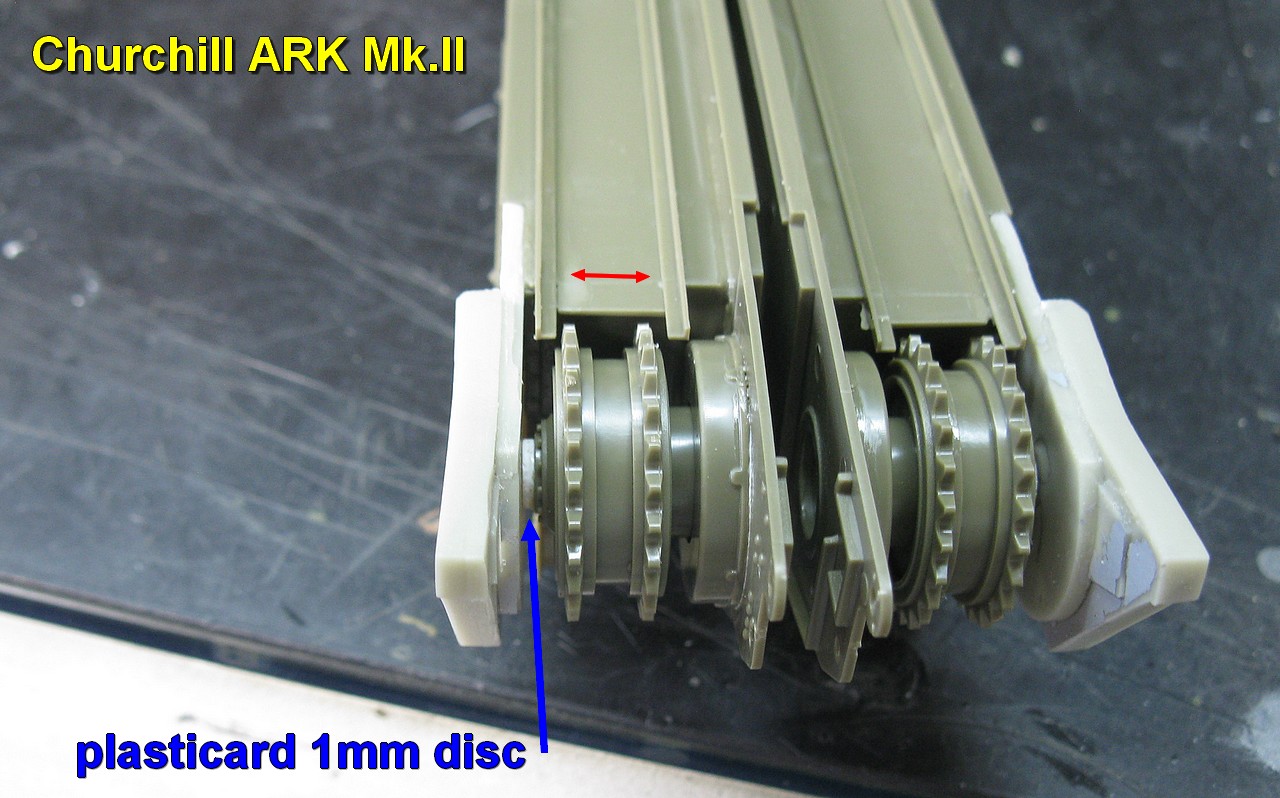
One thing that always bothered me when building AFV Churchills was the sprockets had play when installed in the rear of the hulls. I will try to resolve this gap by applying a 1 mm thick plasticard disc to each sprocket. Look at the diagram below: I will apply the disc (cut with a punch-and-die) to the blue markings...
 |
| The problem and the solution... |
 |
| Let's test in place... |
 |
| First, in the rear of Churchill ARK Mk.I... skirts in plastic... |
 |
| And the 1mm discs fit perfectly... |
 |
| Now, the armoured skirts for the Churchill ARK Mk.II... Resin parts with arms for the ramps... |
 |
| Like a glove!! |
 |
| Suspensions ready!! |
 |
| And with the suspensions ready, we can start closing the hulls. Squaring here is fundamental and totally necessary!!! |
 |
| Front view...Our Churchills are starting to look like tanks... |
The ARK Churchills had no armament on the front glacis. I will seal the gun openings with a thin strip of plasticard (0.3 mm) to be able to better visualize this detail in the following steps...
 |
| Churchills front glacis... |
 |
| Left, the late version (Churchill Mk.III hull for ARK Mk.II) Right, the early version (Churchill Mk.I hull for ARK Mk.I) Notice the openings closed with thin plasticard |
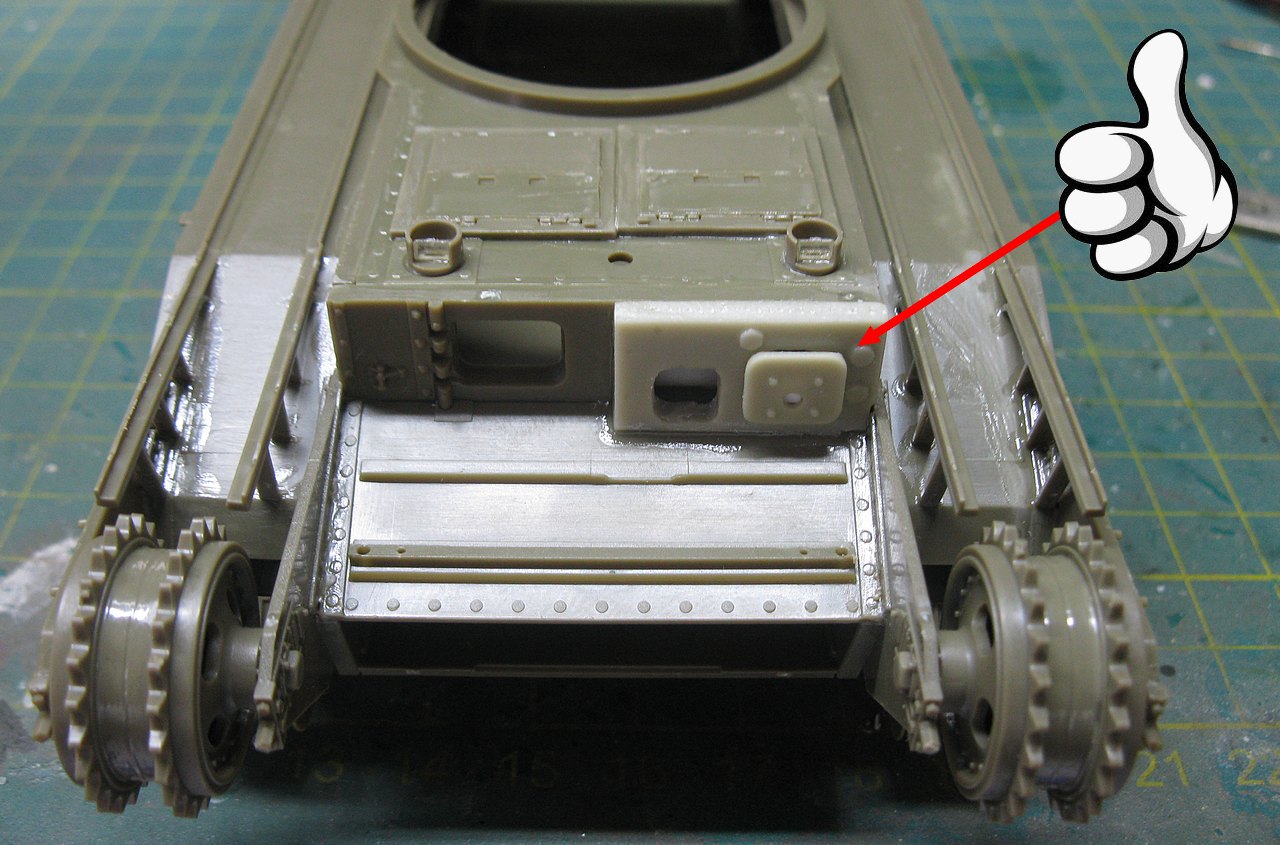
For the early version, Resicast provides the frontal armor of the front glacis, in the shape of two rectangular holes, characteristic of the Churchill Mk.I with a 3-inch howitzer. in the hull. There is also a rectangular shield for the telescopic sight, but the extender for this sight (red arrow) does not come in the kit. I made this piece with a rectangular piece of styrene from Plastruct. See below:
 |
| Early version left Late version, right. |
 |
| The front glacis of the Churchill Mk.I hull. Notice the sight extender in place (red arrow) The telescope shield will be installed there... |
 |
| The telescope shield in position... Although it is a Mk.I hull, it has undergone upgrade work, with track guides and rectangular air filters. A true Frankenstein... |
 |
| The two hulls, Mk.I and Mk.III. The detail of the location of the weapons on the front glacis is what makes all the difference... Front left view |
 |
| The two hulls, Mk.I and Mk.III. As the Mk.I is a reworked hull, the differences are in the rear armored skirts... |
 |
| Next step: close the front hull!! |
Until now, the construction of the two models has continued in parallel. But now, let's focus on a specific model, to pay more attention to the details of each version. Firstly, the Churchill Mk. I (reworked) ARK I.
 |
| Closing the turret hole. As the kit does not have interior details, I will close the two hatch leaves. Notice the exhausts of the Mk. I, without silencers... They must have made one hell of a noise!! Notice the red arrow: reinforcement with plasticard for the internal area of the hatches. |
 |
| Internal reinforcement of the hatches: plasticard glued with gel superglue |
 |
| And the "cover" of the turret hole in position... left top view |
 |
| Right view. Notice the air filters in position: a Mk.I hull reworked!!! |
 |
| Tracks in place. left view |
 |
| Right view... |
With the hull ready, we will now attack the bridge system apparatus. Starting with the Churchill ARK Mk I ramps. The Resicast conversion kit comes with parts that allow you to choose between long and short ramp versions. I will build the long ramp model. And the construction began with a frisson: the chassis ramps have internal reinforcement ribs and my Resicast kit was missing two of these pieces. Man, this sucks!!!
 |
| I need eight segments of I-beam reinforcements. The kit only provided six... Plastruct to the rescue!! |
 |
| I now have eight segments of I-shaped reinforcement. Relief!! |
 |
| The The I-shaped reinforcements installed in position in the central chassis ramps... |
 |
| Installing the hinge end portions... |
With the two chassis ramps ready, we will build the base of these ramps. Everything must be meticulously squared to avoid future disasters... The big tip here is to use gel superglue and not normal superglue: the gel type allows you to position the pieces more calmly, by allowing (initial) movement of the pieces...
 |
| Building the cradle for the central ramps... The weights are to keep everything in alignment without distortions. |
 |
| The central structure ready !! |
 |
| The positioning of the vertical posts is the biggest challenge... |
 |
| And testing the ramp cradle on the tank chassis, in dry-run!! Like a glove!!  |
 |
| Right side view |
So, let's glue the cradle to the chassis... You have to be very careful at this stage. Work calmly and methodically, applying small drops of superglue and checking everything. The cradle rests on the tank chassis by rectangular pads (yellow arrows). They must be well aligned and positioned. Start gluing the crib here: minimal amounts of gel superglue to allow perfect alignment. Only then should you glue the vertical posts to the sides of the hull (red arrows).
 |
| So, let's glue the cradle to the chassis... When you are sure of the positioning, "sew" everything together with glue. |
 |
| Applying a little weight for a perfect adaptation of the cradle to the tank... |
 |
| When you are sure of the positioning, "sew" everything together with superglue. |
While the chassis glue dries, let's take care of the ramps... One part at a time, as old Jack said!!!

With the chassis cradle resolved, let's attack the front and rear ramps, now
 |
| Cleaning structural reinforcement parts... |
 |
| My idea is to replace the resin pivot pins provided in the kit by plastic pins, which are much stronger and more resilient... This could save you a lot of hassle in the future... |
 |
| Triangular "eyelashes" on the front portion of the hull made with plasticard |
 |
| These "eyelashes" are very characteristic of early Churchills, such as the Mk.I and Mk.II, without a doubt |
 |
| Installing the front short ramps. Here, I used a popsicle stick as a template (green arrow), to keep everything well aligned and positioned. The gluing of the locking devices is delicate (red arrows). left view |
 |
| The gluing of the locking devices is delicate (yellow arrows). right view. See the photo below, as reference: |
|
| Front lock devices (red and yellow arrows) locked in position. These devices are unlocked by means of a rod (green arrow), which penetrates the front compartment of the tank. font: IWM A70 5-1 |
 |
| Installation of the rods that release the front ramp locking mechanism left view |
 |
| Right view |
Now, let's install the long rear ramps. The supplied resin hooks are simply crude. Let's use thin copper wire to remake something in a more "presentable" way
 |
| New metal hooks and the new ramp pivot pins in plastic. The resin hooks sucks!! |
 |
| The rear ramp hooks with their mooring lines installed... Tommy is very happy!!! |
And now, let's act like a quantum physics scientist: keep the ramps equidistant correctly and keep everything stable (and detachable...) while we tie the cables...
 |
| To stabilize the ramps, we will use a rubber band... Einstein is not sure of the result of the ongoing experimentation... |
 |
| The great detail is to use gel superglue to keep the cables in the exact position (green), to allow the excess wire to be cut. Using masking tape to crimp the cable (yellow). Notice the new hooks made with copper wire locked with pin segments (red) |
 |
| And finally, after everything was installed and checked, our girl looked beautiful and lined up!!! Eisnten is really happy with the results... |
 |
| Almost ready for painting... |
 |
| Churchil ARK Mk I with late tracks... Something isn't right here... |
I'm very, very happy that I got this wonderful kit from AFV Club: Churchill Heavy Cast Steel Box Section Spudded Tracks (#35183)
 |
| Churchill Heavy Cast Steel Box Section Spudded Tracks (#35183) New shoes for our beautiful girl!!! |
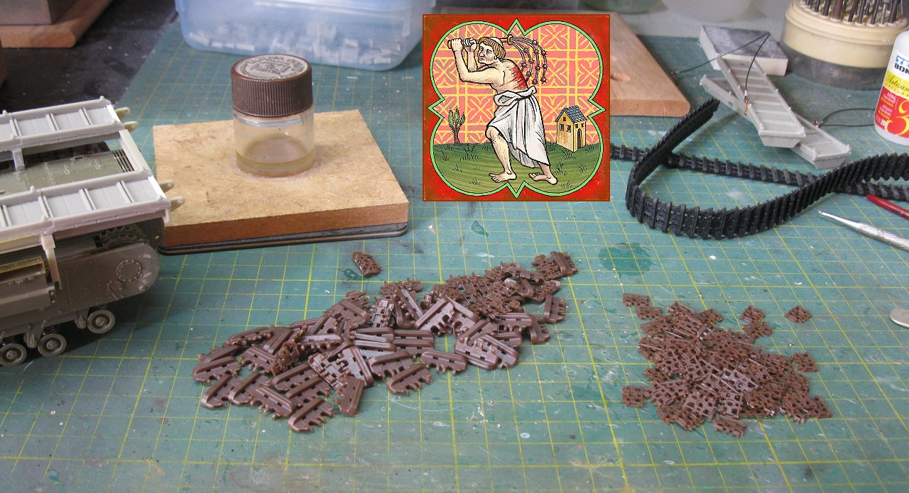
 |
| The reason I HATE link-by-link tracks: A lot of little pieces to be cut, cleaned, fitted and glued!!! But in this case, a necessary evil... |
After removing the vinyl tracks from the tank, let's move on to the self-flagellation part... The good news is that I've already built this LBL track kit and, of ALL the LBL tracks I've ever built in my life, these are the best and least annoying to build... I would even say they are fast...
 |
| The secret: clean cuts of the pieces and assembly in sequence... it hurts less!!! |
 |
| Comparison between tracks... Now, just install it on Churchill. This is relatively easy, as they are movable... |
 |
| Our girl testing her new shoes!! |
 |
| But the pain isn't over yet: building the other track!!! |
Jokes aside and like I said, these AFV Club tracks are really fantastic: they fit together very well and the construction system is easy and quick, especially since I use fusing glues, which can be applied with brushes, in the process. It took me an hour and a half for the whole process, which I think is super quick. But the result, in this case, was worth it for its historical acuity.
 |
| And our girl with the heavy-duty tracks in position. She absolutely loved the new shoes!!! |
 |
| Nothing is more satisfying than seeing a girl happy!! |
Now, let's take care of the Mk.II Italian Pattern version of the Churchill ARK. Let's build the American M1 type ramps. It all starts with the cleaning team, to remove the resin membranes between the ramp beams. A meticulous job, which must be very well done...
 |
| Cleaning team in action. A lot of resin left as waste... |
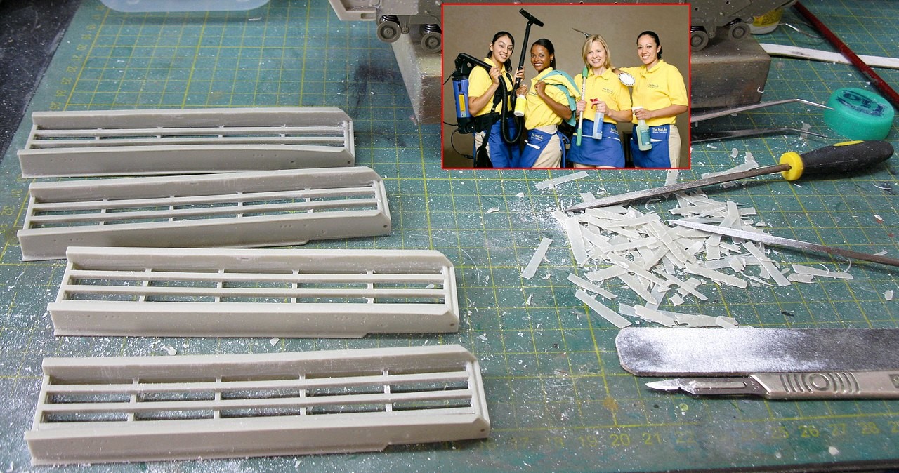 |
| Some of these ramps were slightly twisted, but hot water fixed everything... Completely clean ramps!!! |
 |
| Adding some (fragile) resin details... |
 |
| Ramps ready. The boys are happy with a job well done!! |
 |
| Applying the excellent reticulated PE bases supplied with the kit... |
 |
| Adding the vertical portions of the front ramps. These pieces will be responsible for articulating the ramps. |
 |
| And finally, the side flaps of the frontal ramps. The same process was repeated with the rear ramps |
 |
| Gluing the cross metal beams onto the ramps... |
With the ramps drying, we will build the front and rear articulation arms for the ramps. This step must be carried out meticulously, as a positioning error here would result in crooked and poorly positioned ramps...
 |
| Front arms: first I install the inner parts of the arms (red arrows) and then the horizontal joint bars (green). Everything well squared in the 3 axes... The external parts of the arm will be used, soon (yeloow) Notice the front ramps in the background, drying (blue square)... |
 |
| Front view of front arms: the inner parts of the arms and the horizontal joint bars in perfect squareness. |
 |
| The squareness of the horizontal joint bars must be checked in the vertical and horizontal direction. The use of gel superglue allows these adjustments... |
 |
| With everything adjusted and glued, let's glue the external arms (red)... Always squared!! |
 |
| With the arms assembled, we will build the upper hull guides: measurements provided in the kit must be respected and the side posts (red) of the rails (blue) must be vertical!! |
 |
| And the hull superstructures were practically ready. Everyone is happy!!! |
Now, let's place the ramps on the hull. The Resicast kit provides the pins for these joints in resin, but resin is a very brittle material. Although this kit is not a toy, I will want the ramps to have movement, to allow the kit to be positioned with the ramps extended or raised. I will replace the resin pins with styrene plastic gauge equivalents, as they are much stronger and more reliable.
 |
| Pins of the kit, in resin (red): brittle... Pins made with plastic rods (yellow) : strong!! |
 |
| Plastic pins in position in the front arms... |
 |
| ...and in the rear: most reliable pins! |
 |
| Now, let's install the brackets for the kingposts to support the ramps. The rear first... Notice the pin in plastic piercing the rack. |
 |
| The brackets for the front kingpost with its pin. Notice the front portions applied to the top front deck. |
 |
| The hull, almost ready... |
 |
| Right view of the ARK Mk.II hull |
 |
| In background, the Churchill ARK Mk.I (without rear ramps) and Churchill ARK Mk.II with its ramps installed, in lowered position. |
 |
| The new plastic pins (red) in position... They are just slotted in. left side view |
 |
| Right side view |
 |
| Churchill ARK Mk.II, with the kingposts installed, together with the mooring cables, keeping the ramps in transit position. |
 |
| A beauty, don't you think??? |
 |
| Two simply extravagant Churchill girls!!! |
As I normally do, I try to place our tanks in the correct time and space. This is not a reproduction of ta
nks that existed, but that could have existed in the time and places mentioned. I like to build an orientation plan with the colors and markings of the units involved, and this research seeks to be as correct as possible. First, let's describe the Churchill ARK Mk.I (long rear ramp), built by converting a Churchill Mk.I (reworked) as Armoured Ramp Carrier, with the colors of the glorious 79th Armoured Division ("Hobart's Funnies"), in the evaluation tests of this vehicle concept carried out in test fields at Saxmundham, United Kingdom, in the final days of March, 1944. Our girl has the suggestive name of "HELMSMAN".
 |
| Formation sign of 79th Armoured Division ("Hobart's Funnies") |
 |
| Panzerserra's Colors & Markings profile Churchill ARK Mk.I (long rear ramp) |
And since we are building in parallel, the painting and markings will also be carried out in parallel. So, here are the markings of our Churchill ARK Mk.II (Italian Pattern - M1 ramp), built by the convertion of a Churchill Mk.IV as Armoured Ramp Carrier, with the colors of the 51st Royal Tank Regiment (Leeds Rifles), 25th Army Tank Brigade, 8th Army. Our girl is located in the Gothic Line region, Italy, in the battles of September 1944. As it is a bridge vehicle, it is only fair that it be called the "TOWER BRIDGE", so significant to the English, by Saint George!!!
 |
| Formation sign and Arms of Service of 25th Army Tank Brigade and 51st Royal Tank Regiment (Leeds Rifles) (left to right) |
 |
| Panzerserra's Colors & Markings profile Churchill ARK Mk.II (Italian Pattern) |
But enough talk and let's heat up the airbrush!!! Shades of green, on our girls...
 |
| The ramps of both vehicles are detachable, to allow painting... |
 |
| Still a single shade of green, very boring... |
While waiting for the paint of base color to dry, I studied the lines of the vehicles and, although the instructions make no mention of it, I wondered how the crew could open the turret hole hatches in the hull without a handle. I looked in the photos of the real vehicles and I couldn't find this detail... Well, if I were an engineer from REME or the 79th AD, I would certainly install two handles on these hatches... And that's what I did: late, but I think still in time to fix this detail.
 |
| Sorry, Captain. I forgot to install the hatch handles.... |
Working with shades of green. Note the handles, made with copper wire. I purposely made the handles differently from the standard handles on the Churchills, as these hatches were an off-line adaptation of the tank.
 |
| Calm down, Captain...everything can be fixed.... |
 |
| Shades of green,,, |
 |
| The same repair being done on the Churchill ARK Mk.II in parallel with the tonal variations in painting. |
 |
| The handles will be touched up with a fine brush. No problem after all! |
Now, the markings... Fortunately, I have a well-stocked box of extra decals, but it is always necessary to make a specific decal. The markings of the 25th ATB, the 51th RTR and the private names were made with a laser printer using white and transparent decals, after artwork in CorelDraw. Here are the results.
 |
| Panzerserra decals... |
 |
| The two ARK girls waiting for their props... |
 |
| Churchill ARK MK.I HELMSMAN top front left view |
 |
| Churchill ARK MK.I HELMSMAN left side view |
 |
| Churchill ARK MK.I HELMSMAN right side view |
 |
| Churchill ARK MK.I HELMSMAN front view |
 |
| Churchill ARK MK.I HELMSMAN rear view |
 |
| Churchill ARK MK.II TOWER BRIDGE top front view |
 |
| Churchill ARK MK.II TOWER BRIDGE left side view |
 |
| Churchill ARK MK.II TOWER BRIDGE right side view |
 |
| Churchill ARK MK.II TOWER BRIDGE front view |
 |
| Churchill ARK MK.II TOWER BRIDGE rear view |
 |
| Churchill ARK MK.II TOWER BRIDGE top rear view |
I was forgetting the steel wire ropes that Churchills carry on the sides of their hulls. Let's then build them, as per the instructions: cut a 110 mm segment of the wire supplied (very good) by AFV and glue its ends to the cable eyelets, with a minimum amount of superglue. Easy!!
 |
| Building the steel wire ropes... |
 |
| And the finished steel wire ropes, ready to be installed... |
But I had forgotten that the measurements provided by AFV are wrong: the steel wire rope is short!! The 110 mm are not enough to fit the cable eyelets onto their respective pins on the chassis. The solution was to install another pin, older than the original (almost 7mm), made with stretched sprue. A minimum of work, but here's a warning...
 |
| The steel wire rope in position... The 110 mm of thread is too short to fit the original pin (red). Note the new pin made from stretched sprue (green), installed prior to the original pin. Churchill ARK Mk.II - left side |
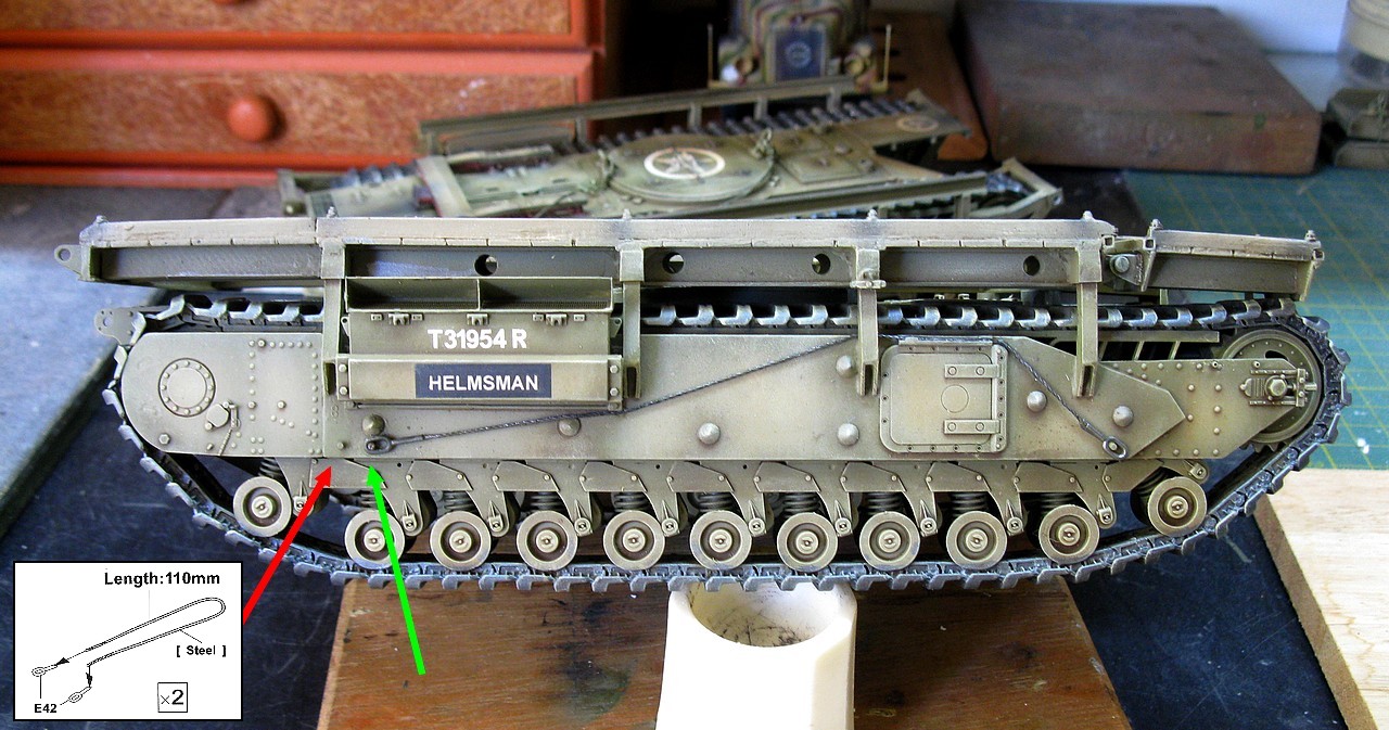 |
| And the same problem with the Churchill ARK Mk.I steel wire ropes |
 |
| But the work of repairing the problem is worth it!! |
And with that, after a stage of weathering and dirt, I can say that our girls are ready for action!! Hierarchically, let's first get to know the pioneering Churchill ARK Mk.I (long rear ramp) "HELMSMAN" with the colors of the 79th Armoured Division ("Hobart's Funnies"), at the time of the evaluation trials, in test fields at Saxmundham, United Kingdom, in the final days of March, 1944.
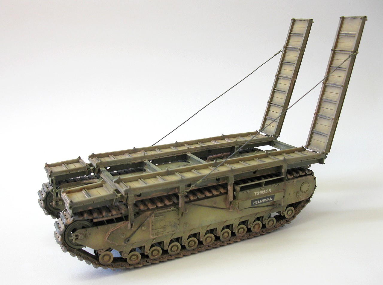 |
| Churchill ARK Mk.I (long rear ramp) "HELMSMAN" 79th Armoured Division - Saxmundham, United Kingdom late March, 1944. |
 |
| Churchill ARK Mk.I (long rear ramp) "HELMSMAN" front left view |
 |
| Churchill ARK Mk.I (long rear ramp) "HELMSMAN" left view |
 |
| Churchill ARK Mk.I (long rear ramp) "HELMSMAN" rear left view |
 |
| Churchill ARK Mk.I (long rear ramp) "HELMSMAN" rear view |
 |
| Churchill ARK Mk.I (long rear ramp) "HELMSMAN" rear right view |
 |
| Churchill ARK Mk.I (long rear ramp) "HELMSMAN" right view |
 |
| Churchill ARK Mk.I (long rear ramp) "HELMSMAN" right top view |
 |
| Churchill ARK Mk.I (long rear ramp) "HELMSMAN" front right view |
 |
| Churchill ARK Mk.I (long rear ramp) "HELMSMAN" with Kojak, in a size comparison photo. |
 |
| Churchill ARK Mk.I (long rear ramp) "HELMSMAN" 79th Armoured Division - Saxmundham, United Kingdom late March, 1944. |
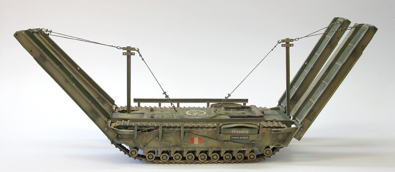
And now, her younger and more powerful sister: Churchill ARK Mk.II (Italian Pattern - M1 ramp) "TOWER BRIDGE", with the markings of the 51st Royal Tank Regiment (Leeds Rifles), 25th Army Tank Brigade, 8th Army. She presents herself with the markings used by the English in the Battle for Gothic Line region, Italy, in September 1944.
 |
Churchill ARK Mk.II (Italian Pattern - M1 ramp) "TOWER BRIDGE" 51st Royal Tank Regiment (Leeds Rifles) 25th Army Tank Brigade - 8th Army. Gothic Line, Italy - September 1944. |
 |
| Churchill ARK Mk.II (Italian Pattern - M1 ramp) "TOWER BRIDGE" front left view |
 |
| Churchill ARK Mk.II (Italian Pattern - M1 ramp) "TOWER BRIDGE" left view |
 |
| Churchill ARK Mk.II (Italian Pattern - M1 ramp) "TOWER BRIDGE" rear left view |
 |
| Churchill ARK Mk.II (Italian Pattern - M1 ramp) "TOWER BRIDGE" front right view |
 |
| Churchill ARK Mk.II (Italian Pattern - M1 ramp) "TOWER BRIDGE" top right view |
 |
| Churchill ARK Mk.II (Italian Pattern - M1 ramp) "TOWER BRIDGE" right view . Kojak is very proud of his work!!! |
 |
| The two Churchills ARKs of the project!! Huge girls!!! |
 |
Churchill ARK Mk.II (Italian Pattern - M1 ramp) "TOWER BRIDGE" 51st Royal Tank Regiment (Leeds Rifles) 25th Army Tank Brigade - 8th Army. Gothic Line, Italy - September 1944. |
Thank you for following this
entire report, colleagues!!
A big hug and see you next time!!