Brave Poilus!!
Mes amies...Today we are going to know a little about what can be considered one of the cars that originated the concept of "aggressive" self-propelled artillery, such as the Soviets' Su and the Germans' Stugs... Let's go back in time, in the muddy and cruel WWI and we meet with the french prototype Renault FT 17 75BS tank.
 |
| Colorized picture of Renault FT 17 75BS, prototype of the "artillery tank" with the 75mm BS gun in the front hull |
History:
The artillery is known as "The King of the Battlefield". And never has this been so exemplified as in the bloody fields of Europe in the WWI... The amount of projectiles that were fired by the countless cannons, mortars and howitzers of all the powers involved in the conflict is unimaginable. And all this artillery barrage convulsed the terrain of the battlefield, And all this artillery barrage convulsed the terrain of the battlefield, transforming the soil of the battlefield into a real challenge to be traversed by men, animals, machines and equipment.
 |
Passchendaele battlefield and craters in which man often drown. Third Battle of Ypres , July to November 1917, Belgium |
At the beginning of the WWI, France (like all other countries) used teams of horses to pull artillery pieces, but with the increase in the calibers (and weight...) of the guns and materials involved, as well as the terrain, which was convulsed by enemy artillery, the animal traction became increasingly complicated, with the animals being easy targets and not supporting the load imposed on them.
With the advent from the first sketches of mechanization at the front, with the presence of trucks and agricultural tractors adapted to be artillery tractors, there was an improvement in the situation, but the logical solution was to provide the artillery with self-propelled capacity.
This (logical) concept was fought at first, mainly in the minds of old Generals with mentalities rooted in old principles. The massive advances of infantry units against automatic weapons was bloody proof of the obtuseness of ancient tactics in the face of modern weapons...and exacted a terrible price.
Something had to be done...Wheeled vehicles faced great problems in difficult terrain...the few and primitive agricultural tractors with tracks used as artillery tractors proved to be much more useful for the task, being seen as a path to be followed by the military.
In France, the Ministry of Munitions and the French Army High Command have researched almost every possible option for moving artillery using tracked vehicles. The conclusion was that there were only two chassis suitable for the task: the Renault FB Artillery Portee and Schneider CD tractor. The Char Saint-Chamond had an off-road speed of only 2.5 km/h, so it was considered unsuitable for a quick response to the fluidity of the artillery's tactical situation.
 |
| A French Renault FB Artillery Portee carrying a heavy cannon on the Western front. |
 |
| Schneider CD tractor in trials front view |
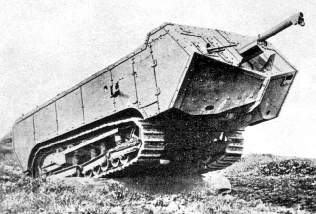 |
| The slow and clumsy char Saint-Chamond tank |
With the satisfactory use of the tank, someone soon imagined equipping these vehicles with more powerful weapons. And so, the concept of self-propelled artillery was born.
Renault FT 17 75BS tank prototype:
The Renault FT light gun tank appeared on the battlefields late in 1917, and in significant numbers in 1918, featuring in a 360° rotating turret a machine gun or a low-velocity 37mm cannon. With combat use, it became evident that although the 37mm gun was quite competent to deal with light fortifications, a weapon that delivered greater explosive weight was needed to attack more elaborate fortified positions.
 |
| Takom (#TAK1003) kit box art |
In July 1917, General Estienne, known as "Father of the French Tank Corps", specified that a vehicle should be developed using the chassis of the new Renault FT-17 light tank, carrying a 75mm Blockhaus Schneider (BS) gun. The 75mm BS gun was originally a short-range demolition gun, which was mounted on the side of the Schneider CA1 tank.
 |
| Schneider CA1 at the head of the ranks of French troops. Notice the 75 mm Blockhaus Schneider (BS) gun in the front right side of the vehicle |
Although the 75 mm BS gun had a short effective range with low projectile velocity, its small dimensions, combined with light weight and high rate of fire made it attractive as the main weapon of an FT fire support tank.
 |
| 75 mm Blockhaus Schneider (BS) gun 3/4 front view Musée de l'Armée aux Invalides - Paris, France. |
 |
| 75 mm Blockhaus Schneider (BS) gun 3/4 rear view Musée de l'Armée aux Invalides - Paris, France. |
 |
| 75 mm Blockhaus Schneider (BS) gun 3/4 front view Musée des Blindes - Saumur, France. |
|
75mm Blockhaus Schneider (BS) gun |
|
|
caliber |
75mm |
|
barrel length
(caliber) |
L/9.5 (rifled) |
effective elevation |
-10° to +30° |
|
traverse |
40° (20°+20°) |
|
projectile weight |
5.55 Kg |
|
muzzle velocity |
200 m/sec |
|
maximum range |
2.100m |
|
effective range |
600m |
|
weight of gun (firing
position) |
210 Kg |
|
rate of fire |
4-6 rounds/min |
In response to the War Ministry's request, Renault itself built a single prototype, based on the chassis and suspension of the light tank FT-17, but with a strange and improvised look box-shaped upper hull. An interesting detail was the presence of the main armament installed in a low position, in the forward portion of the hull, with limited drift.
 |
| Renault FT 17 BS 75 tank prototype Notice the armament in the tank's nose... Trials in France, 1919. 3/4 front right view. |
 |
| Renault FT 17 BS 75 tank prototype right side view. The only two known (this and above) pics (so far) of this model... Trials in France, 1919. |
This design, without a doubt, can be considered the conceptual predecessor of what would be the powerful Russian and German tank destroyers of WW II, like the Su-85 and Stugs III and IV.
During the trials with the prototype, the vehicle proved to be unstable and clumsy to drive, thanks to its high profile, which greatly raised center of gravity. The Commander/driver, moved up and to the middle of the vehicle, had a 360° view, but it was very limited by the small size of the vision slits of the stocky fixed quadrangular cupola.
 |
| Renault FT 17 75BS Commander/driver cupola Notice the small sizes of vision slits |
Worse was the position of the two gunners of the 75mm BS gun, which were squeezed into a narrow and awkward battle stations in the front hull. In general, the behavior in field of the prototype did not meet expectations...
The Char de Combat C-2 was a design developed by Peugeot in 1918, to compete again with Renault's FT17 75BS, using the same main gun, the BS 75mm.
 |
| Peugeot Char de Combat C-2 Notice the gun, the same BS 75mm. 3/4 front view |
 |
| Peugeot Char de Combat C-2 3/4 rear view |
Although the concept of using a 75mm cannon was well accepted, but both the Renault FT 17 75BS and the Peugeot C-2 were not accepted for production, the version that was produced (1918) being a much more simplified version FT 75 BS, as it kept the same hull as the FT17 light tank, with the replacement of the 360° rotating turret for a fixed octogonal turret, carrying the approved 75mm BS gun. But this is another history...
 |
| Renault FT 75 BS in trials |
 |
| Renault FT 75 BS in trials |
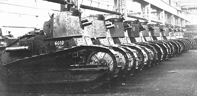 |
| Line of brand new Renaults FT 75 BS , waiting delivery to combat units. |
It is not known the fate of the only prototype built, after its rejection.
Specs:
| Renault FT 17 75BS tank prototype | |
|---|---|
| Type | self-propelled artillery |
| Place of origin | France |
| Service history | |
| In service | single prototype |
| Used by | France |
| Designed |
|
| Specifications | |
| Mass | 6.7 tonnes |
| Length | 5.003 mm with tail 4.114 mm without tail |
| Width | 1.714 mm |
| Height | 2.730 mm |
| Crew | 3 (Commander/driver + 2 gunners) |
| Armor | 8 to 16 mm |
Main armament | 75mm Blockhaus Schneider (BS) gun |
| Engine | Renault 4-cyl, 4.5 litre, Gasoline (petrol); Zenith carburettor, Magneto ignition 39 hp @ 1500rpm |
| Power/weight | 5 hp/t (3.7 kW/t) |
| Transmission | Sliding gear; 4 forward x 1 reverse. Main clutch plus two subsidiary clutches (tracks) for steering |
| Suspension | vertical springs |
| Fuel capacity | 84 litres (about 8 hs) |
Operational.range | 35 km |
| Maximum speed | 7,5 km/h road 3,5 Km/h off road |
The kit:
To do this commission work, I received this 3d printed kit from my client, for the construction: Renault FT-17 75BS prototype tank (R3D-220), from Vargas Scale Models.
 |
| Vargas Scale Models kit (#R3D-220) box illustration |
 |
| Kojak with printed parts of Vargas kit... Notice the kit name plate folded...maybe a greater care with the pieces after printing would prevent this... |
 |
| Kit box contents... |
 |
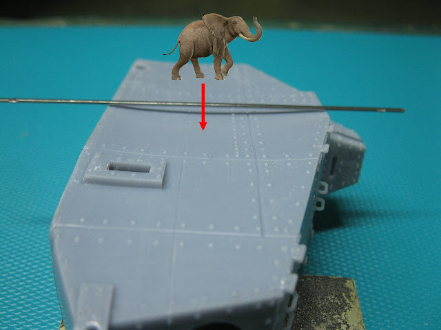
| Right side of the hull, in front view. Notice the bulging of the vehicle's surface, as if an elephant were on that face... |
 |
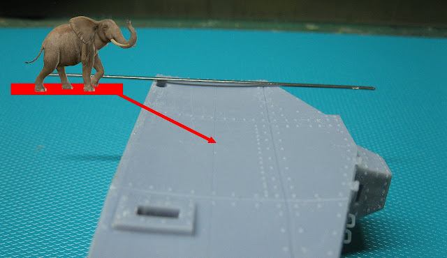
| The worst degree of deformation is in the vehicle midline, vertically and horizontally... No good, Vargas!!! |
 |
| Right side - front portion As you approach the ends, the deformation becomes smaller... |
 |
| Right side - mid portion The greatest degree of deformation... |
 |
| Right side - rear portion Deformation is reduced... |
 |
| Left side - front portion The deformation is a little smaller, as on the left side... |
 |
| Left side - mid portion The deformation is huge!! |
 |
| Left side - rear portion Deformation decreases again, as on the other side |
 |
| In a frontal view, the tank has a waistline that reminds someone... But in a kit, that's pretty ugly!! 3/4 front right view |
 |
| Really, the thing is very deformed!! 3/4 rear left view |
 |
| The rivets lines graphically show the degree of deformity!! |
 |
| The bottom of the hull is glued at the factory, with superglue. Excess of material and dripping glue.. A little more care, Vargas, please... |
 |
| But Kojak is not intimidated by certain problems... |
 |
| Fractured part in the sid tail (red arrow) |
 |
| In addition to the Marilyn Monroe-like waist, the bottom had a downward bulge... Ouch...the thing promises!! |
 |
| Trying to rectify the bottom surface... The lower portion of the hull does not have any rivet or plate joining details... |
 |
| First step: open the lower hull to gain acess to te tank's interior... Using my rotatory tool in my Dremel. A very risc procedure... |
 |
| Cutting four 2mm thick plasticard parts for the reinforcements... |
 |
| The hull with walls after use of hot and cold water. Notice the reinforcements... |
 |
| The reinforcements installed and "sewn" with superglue, throughout the contact area... This will keep the walls aligned and stable... |
 |
| Reinforcement done.. No more a curvy girl, but a smooth, perpendicular and straight hull. Like a modern top model: a pool cue!! |
 |
| Right side... Straight like a board!!! The bottom was closed with 0,3mm thin plasticard |
 |
| Left side... Straight like a board!!! |
 |
| Testing the flat surface!! Mid position in the left side... |
 |
| All ok!!! |
 |
| Testing the flat surface!! Mid position in the right side... |
 |
| After this "frissom", everything seems to be back to normal... Sponsons in position, in perfect perpendicular position... |
 |
| 3/4 front left view... I think everything is correct now... |
 |
| Much better!! |
 |
| Now it's time for the details... The 75mm Schneider Mortar |
 |
| Let's rectify the hole in the gun... |
With the construction of the kit, I realized that the quality of the kit's printing leaves something to be desired... The presence of the printing lines really bothers me... Their removal would almost be a complete reconstruction of the kit, which is not the case. of this article.
But the big flaw would be in the dimensions and shape: the hull rivets are too big and deformed; the seams between the armor plates are wrong in the kit.
And the inexplicable thing is that these lines are perfectly visible in the existing photos, as well as the mistakes made by the manufacturer, such the centralized (...and wrong) position of the Commander's cupola, its shape, the rivets, the vision slits... Worse are the hatches in the front upper part of the hull, with wrong dimensions and positioning.
I hope Vargas Scale Models can and want to correct these flaws, as the kit is expensive. As the kit is by 3D printing, I think the correction is not that difficult... just look carefully at the photos and the 3-way drawings and re-render the model in 3D... Quite different from modifying an expensive one. machined form of an injected kit. See the picture below:
 |
| Some of the kit's most glaring flaws... See below the correct shape of the vehicle |
 |
| Ft 17 75 BS blueprint |
 |
| Another unexplained failure is the absence of the vehicle's manual engine starting system. But the scratch is easy... |
 |
| As kit construction evolves, the "paternity" of future WW II destroyers is evident!! Renault FT 17 75BS tank - left side |
 |
| Renault FT 17 75BS tank - right side |
 |
| Renault FT 17 75BS tank - right rear side view Notice the anti-trench tail installed Details broken in transport are made with white plasticard |
 |
| Renault FT 17 75BS tank - left rear side view Notice the delicate cranks in the tail... |
 |
| Primer Vallejo bronze green, with tones |
 |
| right view of the vehicle |
 |
| left rear view |
 |
| Adding colors to the tracks... |
 |
| Shades of dark-green |
 |
| Vehicle muffler, after basic painting. Severe weathering will not be done on this part, as the vehicle was a prototype of little use... |
 |
| Painting with the application of Pledge, to facilitate the wash... |
 |
| The wash in progression... |
 |
| Wash in old-school way... |
 |
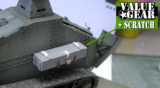
| How about using a Value Gear wooden crate as a tool chest??? Thin plasticard... |
 |
| The padlock was made with plasticard and fine copper wires... |
 |
| The toolbox is in dry-run. The painting will be performed separately from the kit... |
 |
| Painting done! Glued in position!! |
 |
| Final results... Notice the chain in the tank's rear... |
 |
| Right side of the kit... |
 |
| The lovely french maids (Kojak's assistants) approved and loved the skid tail... |
 |
| Starting dust and earth shadows with airbrush... left view |
 |
| Dust and earth shadows with airbrush... right view |
 |
| Renault FT 17 BS 75 tank prototype Trials in France, 1919. |
 |
| Renault FT 17 BS 75 tank prototype upper front left view |
 |
| Renault FT 17 BS 75 tank prototype left view |
 |
| Renault FT 17 BS 75 tank prototype left rear view |
 |
| Renault FT 17 BS 75 tank prototype right rear view |
 |
| Renault FT 17 BS 75 tank prototype upper right rear view |
 |
| Renault FT 17 BS 75 tank prototype right view |
 |
| Renault FT 17 BS 75 tank prototype right front view |
 |
| Renault FT 17 BS 75 tank prototype with Kojak and Rover, the dog. |
 |
| Renault FT 17 BS 75 tank prototype with .Little Willie, in background |
 |
| Sherman II direct vision with Renault FT17 75BS, side by side. |
 |
| Renault FT 17 BS 75 tank prototype Trials in France, 1919. |
Thanks for following the article, guys!!!


Marcos,
ResponderExcluirWhat a shame that you had so many problems. However, your corrections and repairs are a tutorial all their own! I run into Luis Vargas a couple times a year (he lives about 45 minutes up the road from me) and I will relay to him your issues.
Cheers,
Rick
Hi, Rick... Thanks, my friend!!
ExcluirIf he wants the 3 view drawing as a guide, he can feel free... A big hug!!
Hola Panzerserra, de lo que para más de un modelista hubiera sido imposible sacar algo decente, tu has hecho una vez más una maravilla con una "pastilla de jabón deformada" que un tal Vargas ha tenido la poca vergüenza de poner a la venta.
ResponderExcluirYo aún no me explico como puede haber fabricantes que sean capaces de sacar "esa cosa" a la venta... que además me imagino no será nada barata.
Un saludo.
Holla, Juankar...Es una pena, ya que los kits impresos en 3D permiten una solución rápida de sus "maestros", digamos. El kit tiene una suspensión muy buena... Creo que es solo que el fabricante está acertando con estos detalles de agudeza para que la cosa sea excelente. Abrazos!!
ResponderExcluir