
Mesdames et Messieurs...
Today we will meet another pioneer of modern warfare: one of the forerunners of the concept of self-propelled artillery: with you, one of the first attempts to develop an effective self-propelled artillery, the prototype Renault FT-17 Chenilles 75Mle -1897 (Renault FT-17 Tracked 75Mle (1897).

 |
| Final version of Renault FT-17 Chenilles 75mm Mle 1897 prototype - France - 1918 |
History:
We can consider the First World War almost as a laboratory for testing new weapons and new tactical doctrines in the military field. The ubiquitous infantry and artillery were present, but now they faced the new challenges generated by the widespread use of automatic weapons, planes and the massive use of artillery barrages... And all these new factors demanded mobility from the previously static front lines. At the beginning of the conflict, around 1915, the French High Command identified increasing the mobility of artillery as a key point, as animal traction and the primitive wheeled trucks of the beginning of the conflict were ineffective to move and supply artillery across the convulsive terrain of the Western Front.
 |
| Horses pulling heavy howitzers British Royal Artillery - Western front - 1916 |
 |
| French artillery horse drawn - 1914 The gun is a 75mm Mle 1897. Note the number of soldiers and horses for an artillery piece |
 |
| A horse drawn an Obusier de 155 mm C on the road along the Somme Canal - 10 July 1917. |
%20during%20the%20Battle%20of%20Verdun%20..jpg) |
| A heavy artillery tractor truck Latil TAR and his de Bange 155 mm long cannon mle. 1877 resting on your way to Battle of Verdun - 1916. |
 |
| Holt tractor used as artillery tractor by the French Army in the Vosges - Spring 1915. |
 |
A French Renault FB Artillery Portee carrying a heavy cannon on the Western front. |
 |
| Schneider CD artillery tractors loaded onto trucks for transport to the front. Clermont, September - 1918. |
Renault Self-Propelled Guns prototypes:
The most logical way to do this would be to use the chassis of the tank in use. As the Renault FT-17 light tank had been in operation since 1917, we can say that the attempt to install light field guns on these chassis would be a great option, as it would allow for a standardization of the material used and ease of logistics.
 |
| Renault FT 17 light tank Takom kit #1003 box art |
In May 1918, technical studies began for the installation of these cannons in FT-17 chassis without turrets, with the Canon de 75 mm modèle 1897 (75mm Mle 1897 field gun) and the Canon de 105 mle 1913 Schneider (105 mm Mle 1913 field gun) being considered.
 |
| Canon de 75 mm modèle 1897 |
 |
| 75mm Mle 1897 field gun (Imperial War Museum) |
 |
| Canon de 105 mle 1913 Schneider |
 |
| Canon de 105 mm long modèle 1913 Schneider Camp de Saint-Cyr Coëtquidan - France - 1914 |
From 1918, the GHQ of the French Army received and approved these studies. On May, 1918, a specification was issued for the construction of prototypes based on the Renault FT light tank equipped with the 75 mm Mle 1897 field gun and with a crew of 4 (driver/Commander + three gunners), carrying 100 rounds of ammunition and a total weight of 5 - 6 tons. The intention was to build an SPG that could be used for counter-battery fire and in a possible anti-tank artillery role. Lets see:
 |
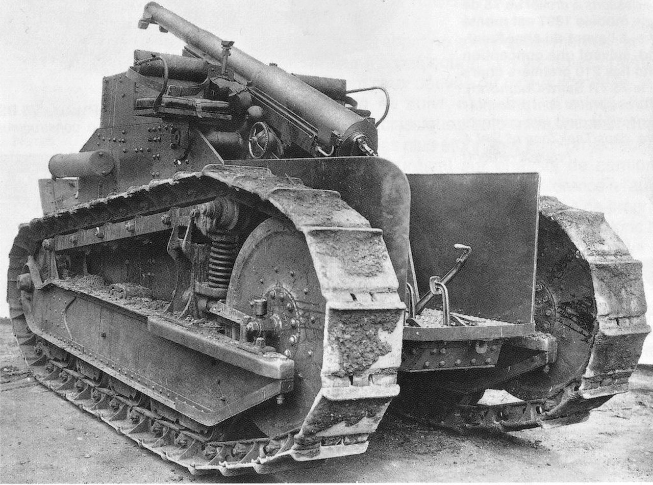
| First version of Renault FT-17 Chenilles 75Mle -1897 in tests at Renault factory testing ground. August - 1918 |
The first version of the vehicle it was extremely minimal, with the removal of the turret and front superstructure of the light tank, with the driver being practically "slotted" between the two tracks of the tank.
 |
| Renault FT-17 Chenilles 75Mle -1897 (early) Notice the driver's station: totally unprotected, including suspensions and tracks, dangerously exposed right on the driver's side. One wrong arm movement and.... |
 |
| Renault FT-17 Chenilles 75Mle -1897 (early) From this angle of view we can see how dangerous the driver's position really is... |
The 75mm Mle (1897) gun was installed just behind and above the driver, firing into the rear of the vehicle, over its tail. The gun elevation was +24° and depression -4°, increasing the maximum range of the weapon (the original gun angulations were −11° to +18°). This range could be extended slightly with the vehicle positioning itself over an obstacle or an elevation.
 |
| The 75mm Mle 1897 aiming in reverse, in maximum depression. Note the absence of the engine cover. |
 |
| Horizontal transverse of 75mm Mle 1897 |
The vehicle's ergonomics were quite awkward, with the driver having to leave his station for the weapon to fire (...before we criticize our French friends, we can't forget that this was repeated years later, with the British Archer Self Propelled Gun 17 pdr Valentine Mk I ).
 |
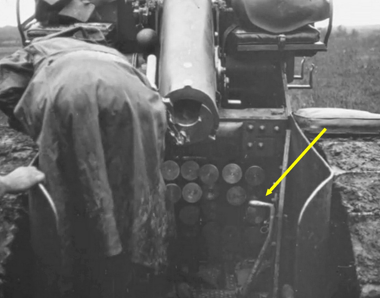
| Renault FT-17 Chenilles 75Mle -1897 ready to open fire, with the weapon at minimum elevation. Notice the gunner (from the back) with his left hand on the trigger, in the breech of the gun. See the next pic, below... |
 |
| Renault FT-17 Chenilles 75Mle -1897 firing. Notice the total recoil of the weapon, with the breech invading the space of the driver. |
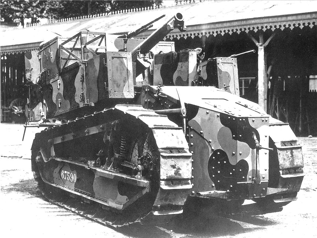
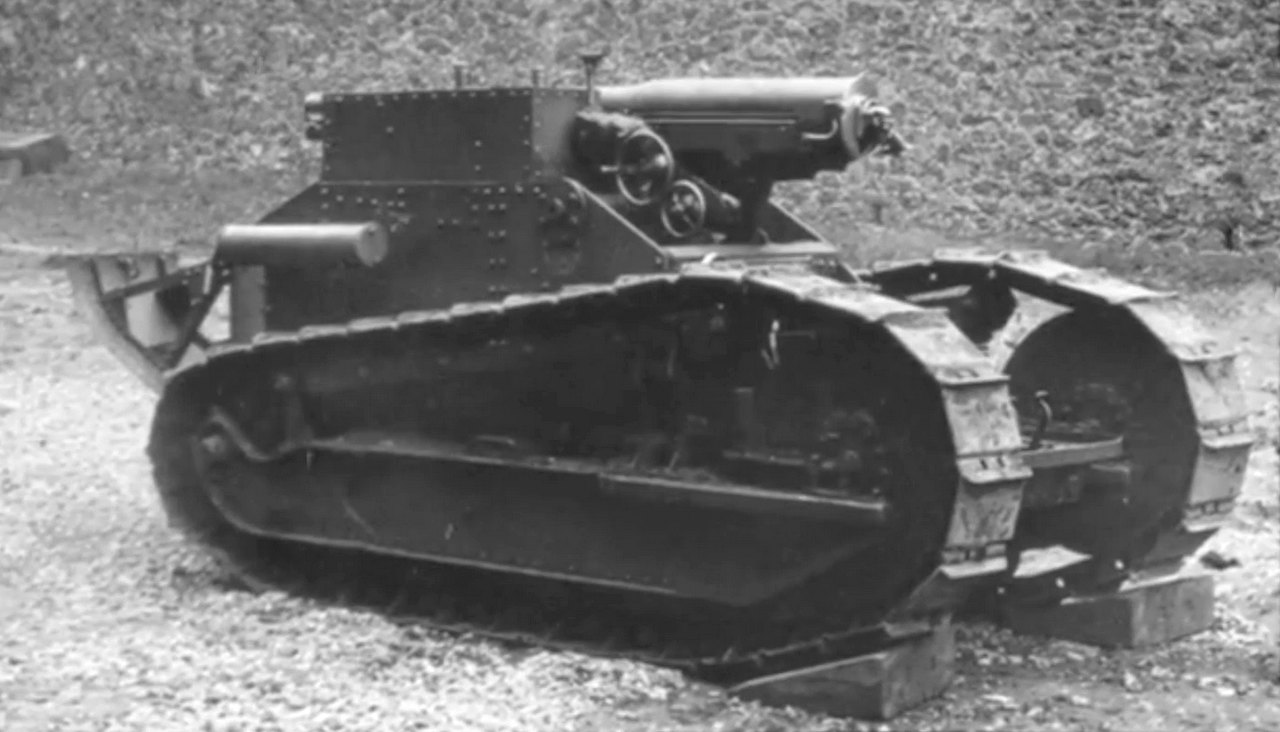
During the tests, the prototype underwent an update, with armored side protections up to the top of the tracks, in the driver's station and the installation of two (totally unprotected) seats on top of the superstructure, for the gunners.
 |
| Renault FT-17 Chenilles 75Mle -1897 "late" Notice the side walls in the driver station and the two seats for the gunners, with the cannon between them, in the top of superestructure. Also note the ammo rack, with a capacity of 40 projectiles, just below the gun. |
 |
| The new driver station... still exposed, but much better protected from tracks and suspensions... |
 |
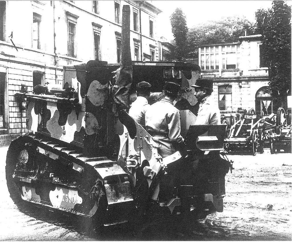
| Renault FT-17 Chenilles 75Mle -1897 "late" roaring in the test field, with full capacity. Driver (red), two gunners (green) two reserve-gunners (deep blue) and a true "tail-end-Charlie" (or Charles...) in the rear skid (light blue). |
The final conclusion of the tests was that although the Renault FT-17 Chenilles 75Mle 1897 presented a stable firing platform and behaved reasonably well in the cross country field, the smaller ammunition carrying capacity and the strange ergonomic arrangement of the handling and driving of the vehicle were very negative factors.
An attempt to remedy this deficiency in the transport of ammunition by the Renault FT-17 Chenilles 75Mle 1897 was the construction of the Renault FT Chenilles porte munitions, but the results of this binomial were not considered satisfactory.
 |
| Renault FT Chenilles porte munitions - prototype |
In the end, the Renault FT-17 Chenilles 75Mle 1897 was not approved for entry into production by the French Army. The ultimate fate of this prototype is uncertain, perhaps being dismantled and reverted to tank-gun standard.
Renault FT Chenilles 105 Mle 1913 Schneider prototype:
 |
| Prototype Renault FT Chenilles 105 Mle 1913 Schneider Notice the radical modification in the light tank profile... |
 |
| Renault FT Chenilles 75 Mle 1897 STAV prototype |
 |
| Renault FT Chenilles 75 Mle 1897 STA prototype - front view Notice the the most functional aspect of the vehicle, with 8mm MG Hotchkiss, for close defense. Also note the engine starter crank in the front of the hull. |
 |
| Renault FT Chenilles 75 Mle 1897 STA prototype - rear view Notice how the crew traveled crammed into the back of the vehicle. The earth spade is raised and 8mm Hotchkiss MG covered with a tarp. |
 |
| Renault FT Chenilles 75 Mle 1897 STA prototype - rear view Notice the crew in firing position The earth spade is lowered and the 8mm Hotchkiss MG ready for action |
Specs:

| Renault Ft-17 Chenilles - 75mm Mle | |
|---|---|
| Type | Self Propelled Gun |
| Place of origin | France |
| Service history | |
| In service | trials only - prototype |
| Used by | France |
| Wars |
|
| Production history | |
| Designed N° built | 1918 one or two prototypes |
| Manufacturer | Renault |
| Specifications | |
| Mass | 6.5 tonnes |
| Length | 5.00 m |
| Width | 1.74 m |
| Height | 2.14 m |
| Crew | 4 = 1 comm/driver + 3 gunners) |
| Armor | 8 mm |
Main armament Rate of fire | 75mm Mle 1897 field gun elevation: +24°; -4º drift: 3° left ; 3° right max. range: 11.000 m 28 rounds/min max. 6 rounds/min practical |
| Engine | Renault 4-cyl, 4.5 litre gas - 39 hp @ 1500rpm |
| Power/weight | 5 hp/t (3.7 kW/t) |
| Transmission | sliding gear; 4 fwd x 1 rev. |
| Suspension | vertical springs |
| Fuel capacity | 95 litres (about 8 hs) |
Operational range | 60 km |
| Max speed | 7 km/h |
The kit:
 |
| Renault FT-17 Chenilles 75mm Mle mod 1897 Vargas Scale Models box art |
 |
| Kojak with another 3D printed by Vargas Scale Models... We are getting specialized in this type of kits... |
 |
| Page one of the instructions. The 75mm projectiles, although shown, are not included in this kit. A suggestion to you, Luis Vargas!!! |
 |
| Page two of the instructions. |
 |
| The tw o FT-17 girls, side by side: the feeder and the killer... The ammo carrier you will see in the next article!!! |

 |
| The tube features drift to the right, mon Commandant!! |
 |
| Printing irregularities (bulbs and depressions) on the surface of the tube of barrel, all around its perimeter... |
 |
| The tube of the cannon warped and full of irregularities in his surface, visible in this photo. I will excise the portion between the red arrows... |
 |
| The "contaminated" tube (red X) and the future "tissue" to be grafted... |
 |
| Preparing the cannon tube glue... |
 |
| The gluing of the muzzle brake to the cannon tube was smoother, without needing the metal pin. Chuck was pleased. |
 |
| The little girl with the shoes on... The gun is waiting... |
 |
| Photogram of the old French Army film, showing the height of the steering levers: much shorter!!! |
 |
| Result: I removed the levers from their positions and redid the insertion holes. I'll shorten the levers!!! Smaller levers, please!! |
 |
| Our characters, tall and short, side by side |
 |
| The kit, with the shorts levers, like the real tank... |
 |
| Note the "depth" of the gun relative to the top of the vehicle's superstructure left side view |
 |
| Another view (right side) |
 |
| But when we look at the kit in profile, we can see that the gun is more "buried" (red line) in the superstructure... Maybe the cannon trunnions are positioned too low (red arrow)... This is causing a problem with the gun elevating wheels (blue arrow) |
 |
| Let's try to correct the height of the gun... |
 |
| A solution to the weapon placement problem... |
 |
| The art and the same step in the kit... |
 |
| The true Renault FT-17 SPG. Notice the absence of step (green arrow) and the base of the seat very close to the metal circle, with rivets (yellow arrow) |
 | ||
| Correction in the positioning of crew seats... A suggestion for Luis Vargas (Vargas Models owner) to upgrade the kit and the new box art!!
Well, after improve the positioning of the gunners' seats, let's return to the cannon. In the last chapter, we noticed that the two wheels of the weapon's elevating mechanism were a little misplaced... Let's move their position back... |

 |
| The idea is retreat those two wheels... |
 |
| Building two new wheels with my punch-and-die tool and plasticard |
 |
| Correction complete: new trunnion base (green arrow) new elevating wheels in a new retruded position (yellow arrows) and the 75mm cannon flush with the vehicle's superstructure.(red arrow) |
 |
| The 75mm cannon at maximum elevation. Note that the elevation adjustment wheels no longer touch the edge of the superstructure (green arrow) |
 |
| All corrections of this step: yellow: seats in the right level green: new elevated trunnions light blue: new elevation wheels |
 |
| And one more tiny but important thing: an engine starting system made with cut hypodermic needles... |
 |
| The driver's station, seen from another angle, showing some interesting details: red: new trunnions, reinforced with dental acrylic light blue and yellow: the wheels of cannon drift adjustment: very delicate and perfect green: the ammo compartment: an incredible delicacy. Well done, Vargas!!! Kojak is very pleased!! |
 |
| Planing the micro-surgery... |
 |
| Cutting the rim (yellow) of the retaining clip, so that we can invert one of the hooks... Be very careful to not feed the Carpet Monster!!! |
 |
| The new left flipped tow hook, with the rim glued in place thanks to a minimal amount of cyanoacrylate.... |
 |
| The new left hook, like the pic... |
 |
| and the old right hook, in position... Now, Jean-Pierre is very pleased!!! |
 |
| And a fox-girl like that deserves a nice tail!!! left view |
 |
| Right view of the skid plate in position... |
 |
| Renault FT-17 Chenilles - 75mm Mle "early" version without driver's station side guards and without crew seats. Notice the toolbox rack |
 |
| Renault FT-17 Chenilles - 75mm Mle "late" version. Notice the driver's station with side guards and two crew seats. Notice the toolbox rack, also. |
 |
| The model 75BS surviving rack. Nothing like a good spare parts box to save the day! As the Law of Conservation of Matter in Modeling says: "In scale models, nothing is lost, everything is transformed"! |
 |
| The problem is that I only have one rack and I need two: Nothing that extra thin Plasticard and Tibetan monk patience can't solve... Scratch time!!!! |
 |
| The new toolbox: Value Gear stuff... Another suggestion to you, Luis!!! |
 |
| The racks in position... waiting the Value Gear box... |
 |
| The racks with Value Gear box. (green arrow) Notice the metal adds in the rear of tool racks...spare parts, too... (red arrows) |
 |
| Renault FT-17 Chenilles - 75mm Mle almost ready!! |
 |
| ...something like this. Colorized photo of the Renault Ft Chenilles 75mm Mle 1897 |
 |
| Renault FT-17 Chenilles - 75mm Mle in green primer, with the gun in maximum elevation left view |
 |
| Renault FT-17 Chenilles - 75mm Mle in green primer, with the gun in minimum elevation |
 |
| Renault FT-17 Chenilles - 75mm Mle rear view |
 |
| Renault FT-17 Chenilles - 75mm Mle in green primer, with the gun in minimum elevation right view |
 |
| Tones of green...left front side |
 |
| Tones of green...left rear side |
 |
| Renault FT-17 Chenilles - 75mm Mle in tones of green - rear right view |
 |
| Renault FT-17 Chenilles - 75mm Mle with shoes and seats painted. Notice the toolbox and rollbags from Value Gear... |
 |
| Small details under painting... |
 |
| Small paint details... right side view |
 |
| The toolbox and rollbags waiting... |
 |
| ...and the toolbox and rollbags, glued in position Soooo coool!! |

 |
| Padlock in the toolbox!! Close up view |
 |
| A little big detail... |
 |
| The keyhole of padlock will be made with a drop of black paint... |
 |
| The girl is almost ready... |
 |
| Crew seats, with seat belts clearly visible (red arrows) Notice the aiming device, too (blue arrow). |
 |
| A schematic (from that time...) drawing of the optical aiming apparatus. |
 |
| Don't lose sight of security!!! right side view |
 |
| Aiming device and seat belts... left side |
 |
| Hooks and chains... |
 |
| Renault FT-17 Chenilles 75 Mle 1897 (late version) Bourges Military Establishment, France - September, 1918. |
 |
| Renault FT-17 Chenilles 75 Mle 1897 - late version front left side view |
 |
| Renault FT-17 Chenilles 75 Mle 1897 - late version front right side view |
 |
| Renault FT-17 Chenilles 75 Mle 1897 - late version left side view - gun in maximum elevation |
 |
| Renault FT-17 Chenilles 75 Mle 1897 - late version left side view - gun in neutral elevation |
 |
| Renault FT-17 Chenilles 75 Mle 1897 - late version rear left side view |
 |
| Renault FT-17 Chenilles 75 Mle 1897 - late version rear right side view |
 |
| Renault FT-17 Chenilles 75 Mle 1897 - late version right side view |
 |
| Renault FT-17 Chenilles 75 Mle 1897 - late version |
 |
| Renault FT-17 Chenilles 75 Mle 1897 - late version with Kojak and Rover, the dog. |
 |
Two pioneers girls from Vargas Scale Models: Renault FT-17 Chenilles 75 Mle 1897 - late version with Char Frot-Turnel-Laffly (armoured steamroller) in background |
 |
| Renault FT-17 Chenilles 75 Mle 1897 (late version) Bourges Military Establishment, France - September, 1918. |

Como sempre, um belo documentário histórico acompanhado de uma montagem e detalhamento de um Mestre.
ResponderExcluirMuito obrigado, Marcos!!! Um grande abraço e a casa é sua!!!
Excluir