The publication of any images or informations related to nazism, fascism or any other totalitarian regimes must be understood as the reproduction of historical accuracy and not as apology to these regimes, leaders or symbols.
ATENÇÃO:
A publicação de qualquer imagem ou informação referentes ao nazismo, fascismo ou quaisquer outros regimes totalitários deve ser entendida como reprodução do rigor histórico e não como apologia a estes regimes, líderes ou símbolos.
Sturmgeschütz IV (StuG IV) - Sd.Kfz. 167 - assault gun and dozer version - case report
Soldaten und Kanoniere !!
Today we will get to know in more detail one of the most efficient weapons developed by the Germans, in WWII. Let's talk about Sturmgeschütz IV , the StuG IV assault gun anda variation made to clean cities after bombing: Stug IV dozer version (Räumschaufel Panzer StuG IV).
A StuG IV assault gun destroyed in an ambush position
France - Summer - 1944.
Sturmgeschütz IV dozer blade (Räumschaufel Panzer StuG IV)
Magdeburg, Germany - 1944.
History:
The Sturmgeschütz IV (StuG IV) (Sd.Kfz. 167), was a Germanassault gun variant of the Panzer IV used in the latter part of the Second World War.
StuG IV early - Ron Volstad - Dragon box art
Panzer IV Ausf G 2 - Ron Volstad - Dragon box art
It was identical in role and concept to the highly successful StuG III assault gun variant of the Panzer III.
StuG III Ausf G - Ron Volstad - Dragon box art
Panzer III Ausf F - Ron Volstad - Dragon box art
Both StuG models were given an exclusively tank destroyer role in German formations and tactical planning in the last two years of the war, greatly augmenting the capability of the dwindling tank force available to the German army on the Eastern and Western fronts.
Development:
The Sturmgeschütz IV resulted from Krupp's effort to supply an assault gun. As Krupp did not build Panzerkampfwagen IIIs, they used the Panzerkampfwagen IV chassis in combination with a slightly modified Sturmgeschütz III superstructure.
The first known proposal for a Sturmgeschütz on the Panzer IV chassis is in Krupp drawing number W1468 dated February 1943. This initial drawing unitized the outdated Sturmgeschütz Ausf. F superstructure on a Panzer IV chassis.
This proposal had a sloped front superstructure with a combat weight of 28.26 tons. Krupp abandoned it in February 1943 because it was too heavy. Plans for the StuG IV were halted.
During the Führer Conference of 19 to 22 August 1943, after the Battle of Kursk, Hitler had seen reports of the StuG III outperforming the Panzer IV when used in an infantry support role and tactical defence. Convinced that a tank-hunter version would be superior to the tank version, Hitler planned to switch Panzer IV production to "Panzerjäger IV" production as soon as possible. It was to mount the same 7.5cm L/70 used for the Panther.
Panther Ausf D - Ron Volstad - Dragon box art
Another manufacturer, Vomag built a prototype Panzerjäger IV with 7.5 cm L/48 gun and demonstrated it on 20 October 1943. It was later re-designated as Jagdpanzer IV Ausf. F.
Jagdpanzer IV L/48 - Ron Volstad - Dragon box art
As the Jagdpanzer IV was already being produced by Vomag, the StuG IV may not have materialized, had it not been for the major disruption of StuG III production, and the scarce supply of the 7.5cm L/70 gun designated for the Jagdpanzer IV.
Jagdpanzer IV L/70 - Ron Volstad - Dragon box art
In November 1943, Alkett, the manufacturer of the StuG III, suffered damage due to an Allied bombing raid. They produced 255 StuG III in October 1943, but in December production fell to just 24 vehicles. A conference held from 6 to 7 December 1943, addressed possible solutions to this problem. Hitler welcomed the suggestion of taking the StuG III superstructure and mounting it on a Panzer IV chassis.
The combat weight was 23000 kg, lighter than the 23900 kg for the StuG III Ausf. G. Between 16 and 17 December 1943, Hitler was shown the StuG IV and approved it. To make up for the large deficit in StuG III production StuG IV production was now given full support.
The StuG IV could be more quickly manufactured than the Jagdpanzer IV at the time. This restarted the Sturmgeschütz IV project. This time, the superstructure of the StuG III Ausf. G was mounted on a Panzer IV chassis 7.
Stug IV late, with Zimmerit and ostketten tracks...
Notice the Teufel (Devil) face painted in the gun's topfblende mantlet.
Russian front - 1944
The major change, resulting from different frame-chassis lengths in PzKpfw III and PzKpfw IV tanks, consisted in enlarging and extension of top front plate of frame-chassis and placing the driver's station in a special, small protruding superstructure (more plainly referred to as a "cage" in a British wartime technical description of that vehicle), fitted with a two part hatch on the top of superstructure. This solution concerning the location of driver's station was caused by the fact that his "workplace" was located more in the front than the remaining part of superstructure (fighting compartment). Although it was possible to shift the location of driver station, this would imply major changes to the drive system and transmission gear, for which there was simply no time. The driver could use two periscopes. StuG III G and StuG IV assault guns are often mistaken for each other.
StuG IV driver's station: Notice the periscopes and the layer of concrete as extra armour in front of the station (red arrow). Compare with the photo below...
A Stug IV with complete set of armour screens (Schürzen)
Notice the prominent driver's "cage" (red arrow) with two periscopes (green arrows).
This vehicle don't use concrete...
The easiest criterion that allows us to assess which vehicle we are dealing with is checking whether the vehicle has the above-mentioned "cage" (i.e. driver's station), as well as identifying the type of drive sprockets, which were different in PzKpfw III and PzKpfw IV. StuG IV guns were fitted with drive sprockets from PzKpfw IV tank. However, they were not fitted with a two-stroke DKW engine moving the turret, which was standard equipment of PzKpfw IV tanks.
Armor thickness of the Stug IV
In June 1944, the production of tank chassis PzKpfw IV Sd Kfz 161/2 Ausf. J with 6 (instead of 8) return rollers was launched; this chassis type was not used for production of StuG IV assault guns until December 1944.
Krupp Works in Magdeburg launched production of StuG IV after having completed the manufacture of PzKpfw IV tanks. In total, more than 1100 vehicles of that type were produced and converted. It was quite a large number in comparison to e.g. production of Tiger family heavy tanks. The number of Tiger I Sd Kfz 181 was slightly bigger, and the production of Tiger II Sd Kfz 182 was half that number.
Manufacture of StuG IV assault guns was to be continued until May 1945. The production plan of November 3, 1944 provided for manufacture of 100 assault guns in that very month. From December 1944 to March 1945 the monthly production was to be at the level of 130 items, in April 100 vehicles and in May 1945 - 50 assault guns.
The first 30 Sturmgeschutz IV Sd Kfz 167 vehicles were manufactured in Nibelungenweike on the basis of series chassis of PzKpfw IV tanks. Some of these vehicles had guns fitted with standard box-type gun mantlet from StuG III Ausf G assault guns; later, topfblende type gun mantlet were applied.
Modifications:
During Stug IV production, numerous modifications of vehicle construction were introduced. Although as early as on 24 January 1944, the General Artillery Inspector stated that additional concrete armour did not significantly improve the armour resistance, combat units still tended to apply concrete. It is interesting to mention that the allies also came to the same conclusions, with studies indicating that concrete reinforcements were not effective, but the crews insisted on applying these layers. The psychological effect of that was the most important factor ...
Stu.G. IV leading a Stu.G. 40 from Stu.Gesch.-Abt.177
probably during the defensive fights of early 1944 on Eastern front.
Notice the rough concrete armour in the front glacis and upper hull
giving a characteristic rounded shape to the vehicle's casemate.
The Stug III in background shows the same characteristic
A Sturmgeschütz III that was captured during January-February 1945
in the Battle of the Bulge by the U.S. Army's 104th Infantry Division,
here seen in service with the 104th Division.
Notice the "rounded" aspect of the Stug's upper hull and the
"absence" of zimmerit (the concrete was applied over the paste).
The americans loved concrete armour...
Concrete armor being installed on an M4 105 tank
A "remnant" of PzKpfw IV chassis tank was an emergency hatch placed in the vehicle floor under wireless operator's station. The above-mentioned station was removed (the radio station was operated by the gunner), and therefore, on 27 March, Krupp Company suggested that the hatch should be welded.
A disabled Sturmgeschütz IV from Heeresgruppe Nord
Army Group North- winter 1944.
Notice the track links welded in the vehicle, as add-armor...
Really, it wasn't just the Allies who did this ...
Order No. 256, dated I May 1944, required the use of wider tracks (the so-called Ostkette) in the winter season. At the end of May 1944 Krupp suggested the use of side armoured screens on the sides of the vehicle, the so-called Schürzen.
A Stug IV with schürzen and ostketten roaring in a dusty road,
somewhere in a Russian front
After the mass production of Panzer IV chassis had been launched, suppliers were not informed in due time whether the chassis would be used for a tank or for an assault gun. Therefore, it was not always possible to carry out the above-mentioned vehicle chassis modifications. Thus, Krupp designed a new type of ammunition container for 8 shells, which could be fitted both in tanks and in assault guns. The minutes of a meeting held in Magdeburg on 20 March 1944 enable us to identify the scope of other changes and modifications:
ammunition container was to be additionally protected with a metal sheet insulating it from the exhaust system
simplified gun mount type SKB 6124
adjustable driver's seat
improved driver's periscopes, better mounts of prismatic elements in the periscopes
machine gun for combating enemy infantry mounted on top of superstructure
additional transport lock for fixed a gun.
In early June 1944, the applied tow hooks (so-called type "C") were replaced with type "S".
"S" hooks
"S" and "C" hooks
A Stug IV with "S" hook in his front glacis...
Two "C" hooks in this Stug III captured.
In mid-June the vehicles started to be fitted with special hooks, the so-called Pilzen, mounted on top of the superstructure. They were intended for mounting an additional fold-up crane with maximum lifting capacity of 2.000kg. To facilitate dismantling of the gun. top part of the superstructure was fixed with screws. In this way, top armour of the superstructure could be easily dismantled and the gun could be removed.
A Stug IV early under gun maintenance. Due to the lack of specialized crane trucks, a 2-ton capacity Behelfskran (auxiliary crane) was designed. The simple device could be used to replace the engine or gun.
Also in June the armour of driver's station was reinforced. In the front, an additional plate (30mm thick) was mounted with six screws. Later, the front armour of the superstructure to the left of the gun (driver's station) and to the right (ammunition container) was reinforced with additional concrete reinforcement. Moreover, an additional armour was used, made of steel plates inclined at the angle of 40-50°, and fixed to the superstructure and front armour of the frame-chassis. On June 24,1944 Krupp submitted a proposal of mounting additional armour.
The crew of this StuG IV has attempted to improve the armour protection on their vehicle.
A short length of Ostketten has been welded to the front of the driver’s position
and covered with a thick metal plate (red arrow). Parts of he superstructure
has been rounded off with a smooth coating of concrete (green arrow).
A Sturmgeschütz IV from a Luftwaffe infantry unit has had the 80mm frontal armour and driver station reinforced by welded-on thick armour plates (red arrows). Notice the concrete rounded layers in the front hull (green arrows)
The driver's station was fitted with an adjustable seat regulated with a bolt. Moreover, the location of prism in right driver's periscope was changed, to limit the so-called "blind zone" to only 5-6 metres in front of the vehicle.
Additional railing was fitted on the rear armour to facilitate transportation of infantry or extra equipment on top of engine compartment. Since August 1944 some of the vehicles were fitted with rotary commander's cupola.
StuG IV cutaway view - crew stations
Originally, StuG IV assault guns had standard armour screens (Schürzen), made of 5-8 mm thick steel plate; later screens made of metal mesh were applied, the so-called Thoma Schürzen.
Vehicles manufactured until the end of September 1944 had armours coated with Zimmerit. Usually whole vehicle was covered with Zimmerit, only with horizontal and vertical ripples.
A Sturmgeschütz IV with a Zimmerit coating identifies it as being from a mid-1944 production batch.
Notice the Schürzen screens and the cammo
Rear view of the same vehicle above.
She's fitted with Rundumfeuer-Maschinengewehr (allround fire machine gun).
Two Flammenvernichter (flame suppressor) pipes have been fitted
in place of the standard exhaust.
Color profile of the StuG IV above.
Notice the beautiful cammo pattern
Gun loader's hatch was changed from two-piece to a single-piece one. Later versions of the vehicles were fitted with vertical exhaust pipes, typical of PzKpfw IV Ausf J tanks. The base of commander's cupola was also modified. Originally it was angular and welded; later a cast element was used, welded to the superstructure and commander's cupola.
In November 1944 an additional lock was added on the front body armour to stabilise the gun during troop movements. Barrel was mounted on the prop at 6° angle of elevation. At the same time rain shields started to be fitted over the prisms of driver's periscope. When it rained or snowed the prisms were not clear. which limited the driver's vision.
Outer fuel line, mounted to tank No. 3, was fitted with addi-tional sheet screen, for protection against mechanical damage.
Also the construction of sideshafts for lateral transmission was reinforced to eliminate the risk of transmission teeth breaking.
Additional guard rails were fitted to avoid the hatch slamming shut when driving. Moreover, an additional hot air nozzle was introduced, leading from the engine to the batteries. The batteries were given additional wooden shields for thermal insulation.
In the same period tow hooks were modified to enable the use of towing shaft
From December 1943 to May 1945, Krupp built 1,108 StuG IVs and converted an additional 31 from battle-damaged Panzer IV hulls. While the number is smaller than the 10,000+ StuG III, the StuG IV supplemented and fought along with StuG III during 1944–45, when they were most needed.
Dozer version:
Were found interesting pictures showing this unique and unarmed Sturmgeschütz equipped with a dozer blade used to clear debris in Magdeburg, after the Allied bombings the Krupp-Gruson Werke A.G. tank plant.
One of the first StuG IV at the Krupp-Gruson Werk AG assembly plant in Magdeburg, December 1943
A mass of 40 cm tank tracks in an assembly shop of the Krupp Grusonwerk A.G.
works in Magdeburg, Germany. Note the StuG IV assault gun in the background.
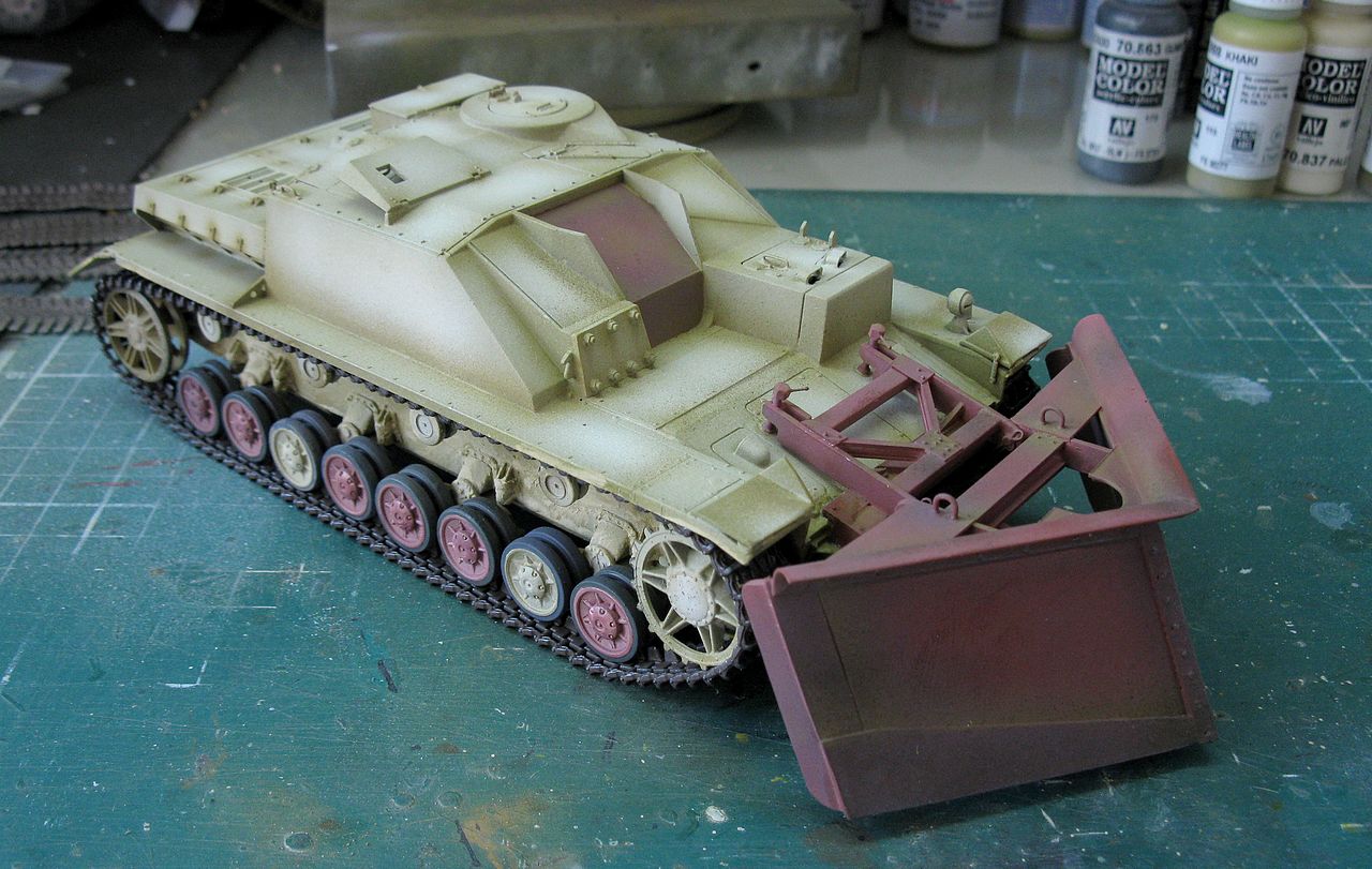
In the picture below, the vehicle seems to have been painted only in the base color (at that time, dark yellow) and the dozer blade appears to be a little darker, perhaps even with an antioxidant background only ....We could imagine the use of a factory test vehicle or even a production specimen, awaiting the arrival of its armament. The correct assumption is that a vehicle as deadly as this one would not be used in a second-line activity unless it was a "dispensable" vehicle due to a defect in armor or even just a concept viability test.
Sturmgeschütz IV equipped with dozer blade
Same vehicle, showing the dozer blade.
At this angle we can see that the blade is fixed, with no lifting mechanism.
Notice that pic it seems to be prior to the photo above, with the dozer blade design still evolving,
without details like the curved baffles at the top of the blade
The StuG IV dozer in action, with the "early" dozer bade design.
Notice the dozer blade is not really movable.
It appears to be bolted to the vehicle's front hull.
The device seems to be very effective ...
In this film below, you can see Magdeburg destroyed by the allied bombers, and the ruins of the Krupp plant. At 33 seconds of film, notice the amount of StuGs IV on the Krupp's production lines.
Maybe those responsible for the factory used a StuG IV chassis without combat conditions (vehicle sent to the factory for repairs or even a vehicle with the armor damaged by fire during bombings) as a civilian support vehicle, like MAN do with his Panther Ausf D Dozer.
Not much else is known about this strange vehicle, only the date in the photo places the "definitive" version on March 30, 1944. And that is more than enough for us to try to reproduce it here ...
For this double project, I will use the Italeri kits Sturmgeschütz IV (# 6223) and a set of metal tracks from Friulmodel ATL-83: PanzerIII / IV Ostkettenfor the assault gun version. The dozer one used the normal tracks, provide by the kit.
Italeri's box art
Friulmodel box art (#ATL-83)
An interesting thing about this kit is that it is a very old kit (1976) with several reboxes and injections, under different brands. But the kit is very well made and injected. Of course, it will present a greater workload, but that is also part of the pleasure of turning this old lady into a contemporary girl !!!
Another interesting detail: In the model world, this vehicle came with the name StuG VI - Sd.Kfz 163. But over time, the name 163 was first erased from the box covers and later changed to the correct StuG IV - Sd.Kfz 167. My kit is from the "middle" period, with no Sd.Kfz number in the box, but still with the wrong one in the instruction booklet.
"Early" Italeri's StuG IV model (#223): notice the Sd.Kfz 163
(below Roman numeral)
"Mid" Italeri's StuG IV model (#6223): notice the absence of Sd.Kfz number (this is my girl!!)
But the first page of the brochure still has the number Sd.Kfz 163...
Notice the stock number 6223
"Late" Italeri's StuG IV model (#6491): notice the number Sd.Kfz 167
But let's get to work .... The first steps are simple and smooth ... in the old Italeri style !!
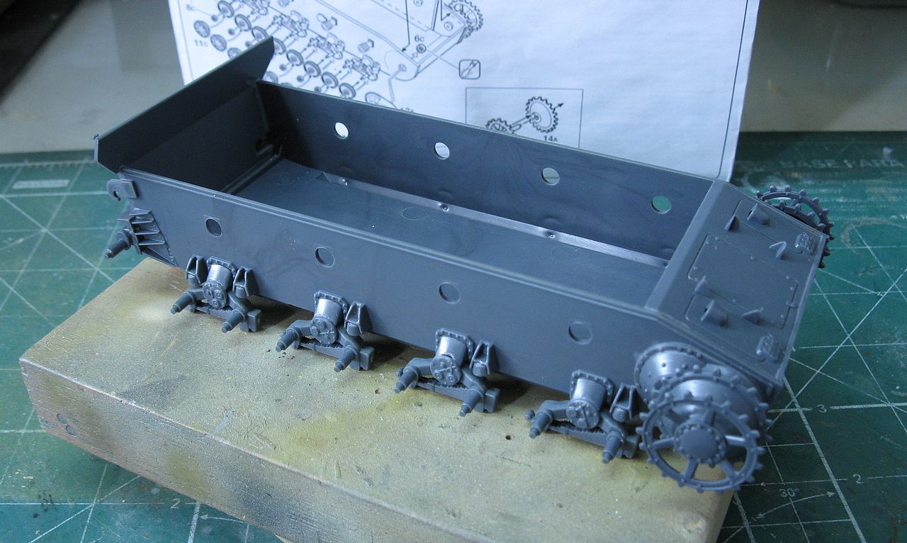
Chassis and suspensions... The drive-sprockets are in dry-run
These are the wrong model, without reinforcements.
They will be replaced by the correct ones ...
Smooth and easy!!
Parallel work saves a lot of time ...
Wheels..lots of wheels to clean-up!!
I love my Dremel...
Cleaning the return rollers...
The return rollers after and before my
magical Dremel!!
The main wheels...64 parts needing cleaning...
Dremel, scalp and sandpaper ...
After and before!!!
The wheels in dry-run... Notice the reinforced drive sprocket
in position and the age of the kit manifesting itself here ...
Shame on you, Mrs. Italeri !!!
But putty is a magical thing...
A dry-run with the wheels...
But, continuing with the building of the double project: An interesting thing is to notice some peculiar details, in the vehicle with the dozer blade ... let's list them, to start the differentiation changes between the girls ...
Presence of additional armor plate bolted to the right portion of the front hull.
Absence of the main gun and possibly obliterated cavity (no ingestion of debris and dust)
Armor of the gunner's MG34 machine gun positioned in the horizontal position.
Absence of the commander's cupola. I speculate that the hatch persists, with a new hinge...
Absence of tools, fire extinguisher and extra wheels
Idler wheel type straight spoke.
Early suspension bumpers
Periscopes primitive type, without covers.
and finally, the dozer and accessories, itself.
Closing the large "mouth" of the 75mm gun and its huge mantlet with 1mm plasticard.
Imagine if that open, the amount of things that could be "ingested"...
The photos of the vehicle do not show this clearly, but if
I were building this vehicle at Magdeburg in 1944, without a doubt, I would do it ...
The big spece closed!!!
Closing the upper huls; the assault gun one by the booklet... and the
dozer version by the logic!!
A small detail that does not appear in the big photo above with the differences of the dozer version: the front flap of the fenders flexed backwards, on their hinges ...
Front fenders flaps flexed backwards...
Space for dozer...
Surgery time: cutting the flaps with care and scalpel. The important is not damage the hinges and flap details ... Notice the suspension bumpers, under "plastic surgery"...
The right fender flap under surgery (red arrows) and the new
suspension bumpers, made with Plastruct (green arrows)
The end of surgical time: two fender flaps ready and the new "early" bumpers...
The girls, side by side...
Notice the flaps from the dozer version...
Cutting the periscopes protections, for dozer girl...
Virgin, in red arrow...and after cut, in green arrow...
They will be glue in the yellow positions...
Some details marked as ready (in clokwise):
The "Big Hole" closed; MG shield in flat position; commander hatch without cupola
idler wheel type straight spoke from Tamiya (yellow one); the new bumpers;
the new periscopes guards and the fender flaps flexed backwards...
Upper vision: notice the new commander hatch hinge
and corrected pin marks in the MG shield from our old friend Italeri...
The assault gun version...
The gals is in rest, now!!!
It's time to making the additional armor bolted to the right front hull of the two StuGs ... These kit from Meng of Nuts and Bolts are simply useful!!!
Starting the dozer: making two blades with very-thin plasticard, as template
Measures in milimeters...
Gluing the two blades together ...
And testing in front of vehicle...
So far...so good...
Side view...
The frame on the front deck seems to me to be rigid (green arrows), with two screws acting as a jack-type to press and lock the frame on the Stug's snout (blue arrows below).
Dozer's frame details...
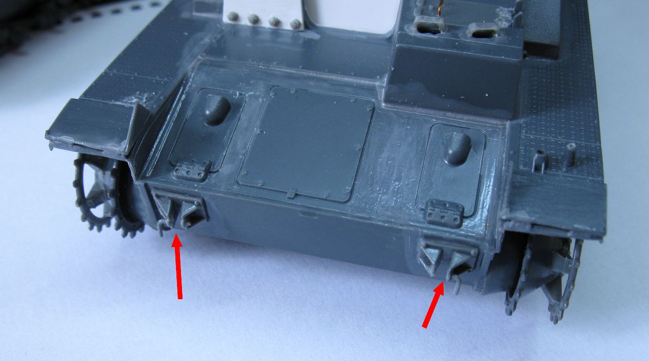
The vehicle has only two hooks on the front glacis and I think that the engineers must have made a system that could be assembled and disassembled using the normal vehicle mountings, in order to be interchangeable with other vehicles of the same standard (see red arrows below):
The StuG's front hull tow hooks. I cut the locking pins
to start the dozer blade frame construction process ...
I am trying to design a structure that could be "fitted" to the front of the vehicle, attached to the two front tow hooks and locked with the two jacks. There could be a pivoting system, suggested by the rounded cuts of the two forks of the frame and a possible access to this adjustment through the rounded cut at the top of the junction between the two "leaves" of the "V" blade dozer (see the red arrows in the picture of real vehicle above). A blade movement would be highly desirable, to relieve the structural pressures of a totally rigid system, for example ... The Panther blade system seems to be quite different, but perhaps following the same principles. I will try to reproduce what is visible and extrapolate what is hidden ...
Damn it, Jim ... I am a Dentist, not an Engineer!!
Sorry, Guys!!!
The first attempts to build the frame, with Plastruct stuff; If everything goes correctly, I will publish a photo with the final measures ...
The frame: top view
The frame: front view
The frame: 3/4 front view
And in place: the frame will be
locked in the front hooks (red arrows) and
with the jacks (vertical red arrows)...
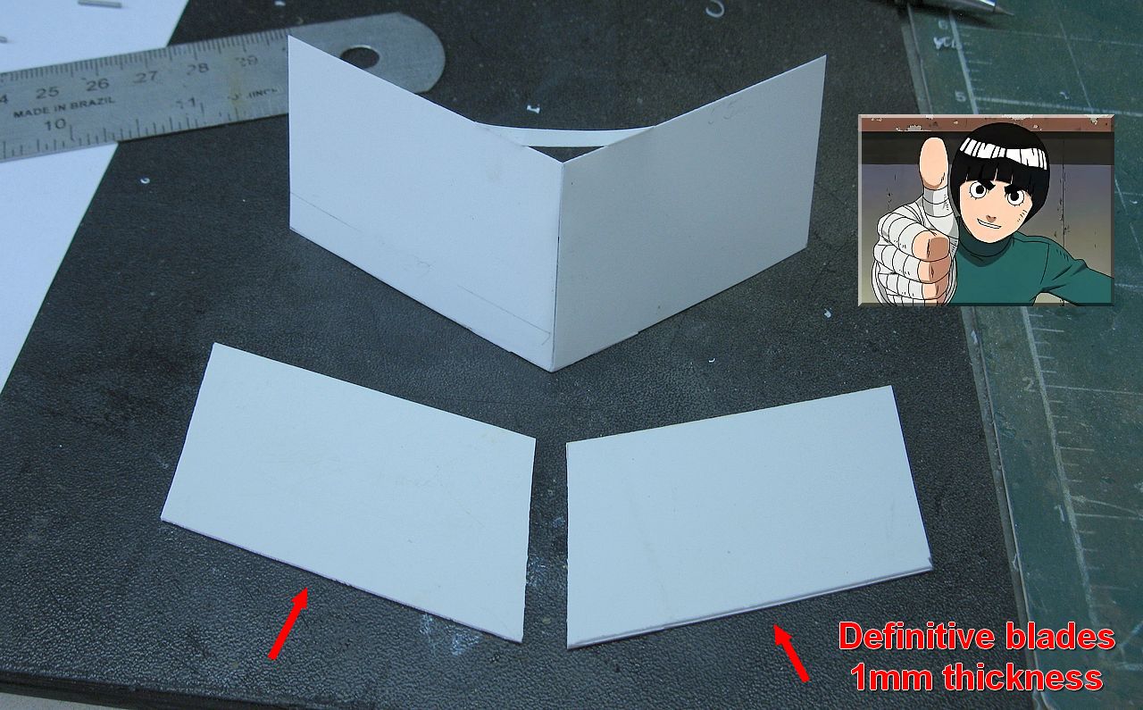
Well ... after testing the shape of the dozer blade, let's build the final one, with a thicker plasticard board (1mm). Here are the pieces already cut ...
The definitive blades cutted for dozer assemble..
As promised, here are the measurements of the dozer blades...
In milimeters, of course!!
And the measurements of the frame, also in millimeters. All of this, of course, the result of my "reverse engineering" ...
Frame for the blade: top view
Frame for the blade: front view
Frame for the blade: 3/4 front view
The blades in posicion, reinforced with
styrene angles of 3mm
For the top "deflectors", I cut a styrene tubing of 7,9mm in the half...
...and sanding the tube, like a diagram in the pic.
The cut and worn tubes glued to the dozer blade top as deflectors (green arrows)
Notice the line carved on the blade, like the splice between the original plates (red arrow)
The dozer is almost there!!
Dozer ready !! Now, it is to build the subframe that joins the dozer
with the frame of the StuG's nose!!
...but first, let's build the reinforcement with a circular cut
of the internal angle of the dozer.
As I said earlier, I choose the "reverse engineering", that is, we will try to reproduce what we see and try to imagine what we do not see, as long as it is mechanically viable ... And don't forget that I am a Doctor, not an Engineer!!!
First stage: position the blade where it should be in relation to the ground and in relation to the front of the vehicle ...
The dozer where it should be in relation to the ground and
in relation to the front of the vehicle ... The hull's frame in position...
I built the first dozer "fork", from the blades to the front of the hull frame ...
I aligned the hull frame with the reinforcement of the dozer fork. (green arrows)
The dozer touching in the front fenders...
THIS WILL NOT BE THE FINAL POSITION OF DOZER ...
just a reference suggested by the real photo.
Dr. McCoy is satisfied with the progress of the treatment ...
Now, I move the dozer to the REAL POSITION and mark on the forks the location of the cut of these same forks ... So far, so good !!!
The dozer in the real position. Notice the space between
the dozer and fenders (red arrows) and
where am I going to cut the forks...
he cut forks, with their rounded ends (green arrows).
Notice the two flat reinforcement plates ...
And the installation of two articulation pins (green arrows).
In my mind, this is how the blade had a certain pivoting movement ...
Testing the movement of the blade.
Damn it, Jim ... It looks like it's working ...
And the final steps of the dozer frame construction. Note, in the pic below, the locking pins on the blade pivots (red arrow) made with thin cooper wire, the two hull frame stabilization "Jacks" (green arrows) and the lower articulated blade locking system (yellow arrows), as well as the lifting hook of this latch (blue arrow).
The blade almost complete...
Side view of the dozer's frame building; The "jacks" in green,
rivets in red and the locking pins in yellow...
Dozer's belly view: the lower locking fork, with its two locks (brlue arrows)
and the pivot pins of this fork (red arrow).
The movement of the lock explained: the lower fork moves in the pivots (red arrows),
with the previous locks fitting the horizontal horizontal bar of the dozer (green arrows).
This system would allow two blade positions ... Rustic, but effective.
Doctor. McCoy liked the solution.
An engineer would definitely do better, but ...
The blade and frames done 99% !
Notice that to adjust the height of the blade, I put some wheels on the suspensions and the blade touches the ground. This is so that everything is well aligned. With the installation of the tracks, the blade will "release" the soil in the thickness of the links of the tracks ... Easy and fast !!!
Big little details: the StuG with wheels and the blade lying in the floor.
With tracks, there will be a free space, with the blade suspended a little bit from the ground .
The building of the "jacks" in detail: the screws are the handles of the acupuncture needles cut in the correct length. The top of the screws are pieces of Plastruct hexagonal rods and the support shoes are plasticard discs cut with punch & die. Acupuncture needles are fanstatic: they serve as screws and aerials ...
The jacks of frontal frame in close-up...,
Indeed, Dr. McCoy is very happy !!
When we observe at the real photos of the dozer, we notice that there is a difference in construction details between the blade of the working photos of the blade that appears in the vehicle's profile photo. This leads us to believe that the blade evolved as the work required. And as the profile photo seems to be the "final" version, the angle of the photo hides some details that the other photos show... Let's see in the image below the different details showing the evolution of the blade:
Early version:
protruding V-shaped reinforcement (red arrow)
dozer narrower, leaving the tracks unprotected (green arrow)
smaller side deflector (light blue arrow)
Late version:
curved deflectors on top of the dozer (yellow arrows)
larger side deflectors and dozer protecting the tracks (orange arrows)
outline markers (blue arrows)
lifting hooks (?) (pink arrow)
Different details showing the evolution of the blade...
So, I think that here is a little bit of my interpretation of the solutions presented. And one of them would be the installation of two hooks to lift the blade with a crane. I know that the lifting cables could be tied to any part of the structure, but the Germans never do anything in half ... So, here are the two lifting hooks that "should" be present, but the photo of the final version shows the top of what could be one of the lifting hooks (pink arrow above). So...
The lifting hooks...
The blade complete, rear view...
The blade complete, belly view...
The dozer apparatus, in the StuG IV snout!!!
StuG IV dozer...
StuG IV dozer - right side view. Dmn it, Jim...I'm almost an Engineer!!!
StuG IV dozer - left side view.
StuG IV dozer - 3/4 rear view.
Damn it, Jim!!! I'm a Doctor and an Engineer!!!
StuG IV dozer blade - cutaway
The two StuG IV girls, side by side!!
Kojak approves!
Well ... the 75mm girl is getting jealous with all the attention the dozer girl is getting ... let's take care of the assault version, now ...
No jealousy, girls ... Both are beautiful !!
Let's see the skirts being worked ...
The build option would be the installation of the tracks ostketten, for deep snow and the maintenance of the schürzen, for additional protection. The problem would be the increase the width of the tracks, typical of ostketten ... Would the schürzen fit ?? Would it be possible?? Let's search in the history ...
StuG IV with ostketten tracks and schürzen...
Yes... They fit!! This is possible!
A posed pic of StuG IV and soldiers. Notice the ostketten tracks and schürzen...
Another StuG IV with ostketten tracks and schürzen...
The assault gun is roaring by a dirty road, in high speed...
No problem with the skirts...
A StuG IV with ostketten tracks and schürzen...
Notice the Devil's face painted on the 75mm gun mantel...
OMG!!! I can't see that kind of image that ideas are already bubbling up ...
First, let's install the rack for schürzen..
I need to install the wider tracks to check the dimensions between the schurzens and the tracks. This is the moment I was postponing: the assembly of the infamous link-by-link tracks ( I really HATE link-by-link tracks...) . The mitigating factor is that they are Friulmodels (ATL-83), which are simply fantastic... but still, a work for modelers in seclusion, worthy of a quarantine !!!
Starting at the beginning: re-drilling the holes in the individual links,
using a 0.4mm drill, as recommended by Friulmodels.
Each link has two perforations ... Each track consists of 103 links and are two tracks.
412 perforations... I love my Dremel !!
103 links later ...
103 links x 2 later...
This German girl is just getting cute ...
Really, these tracks are very stylish ...
Wunderbar !!
Testing the racks with their schürzen .. The release of the tracks is guaranteed only by the action of gravity ... The Italeri kit does not show an adequate bumper at the height of the fenders ...
The skirts in the racks...
The front skirts "touch" the tracks ... Hmmm ... It's not good ...
Searching the actual photos, I noticed that these racks were very fragile, with many photos of these racks simply dismantled in daily combat use. And this is true, especially in the front and aft portions... I thought that the logic would be a reinforcement of these structures so important for the safety of the crew. And it's not that I found something like that, just in the photo of the "Boar's head"! Bingo!!
Notice the structural reinforcements on the supports of the skirts.
More evident detail on the front of the rack (red arrows) ...
As I am a Commander concerned about the safety of my crew, I will ask Kojak to make these reinforcements ...
Field adaptation made by Kojak: structural reinforcements on the struts of the skirts rack ...
Front view
And reinforcements of the rear...
And as Kojak loves to work with steel welding, let's take advantage and make a rack for stowage on the rear deck, so common in the StuG III, but I needed to find out if the StuG IV also had this adaptation ... Bingo !!!
Stowage rack in the rear deck of this destroyed StuG IV (late)
Field adaptation...
Another stowage rack in the rear deck on StuG IV..
Notice the gun in total retraction...
Kojak's work in red arrows...
Notice the spare tracks (green arrows)
Notice the normal track as spare tracks...
Rear view, showing the rear rack (red arrows)
and spare tracks (green arrows)... right view
Left view... Notice the "metal work" in this shot..
The two StuG girls, side by side!!
Starting the painting: Dozer first!!
The vehicle in dark yellow, with tones...
and the new dozer parts in red-oxide. Right side
Left side
The dozer blade in red-oxide
Testing the frame fit...
Tones in the dozer...
Details in the rear view...
Wheels in red-oxide, dark-yellow and exhaust mufflers...
Dozer and assault gun version...
The dozer girl trying on the new shoes ...
The idea would be to use wheels painted in yellow and only red-oxide background.
Left side...
The dozer girl trying on the new shoes ... Right side...
The StuG IV dozer testing the tracks (vinyl ones, Italeri) and with
dozer blade glued in the front hull.
Left side
The StuG IV dozer testing the tracks and with dozer blade glued in the front hull. Right side
Rear view
The height of the blade in relation to the ground was great ...
Left side
Right side!!
The photos of this vehicle do not have any markings ... But it really bothers me a lot ... As the objective of the project is not the exact reproduction of the photo, but the reproduction of the concept vehicle, my idea is that the vehicle has been tested, approved) and photographed ...) and then characterized with markings. The Germans hardly do anything in half...
That I said, let's see the StuG IV dozer operating in Magdeburg, after March 3, 1944. Here is a profile with my markings ideas: number 1, because the vehicle is unique !!
Decals from my spare parts box... Notice the spare wheels in position...
Left side
StuG IV Dozer - vehicle number 1 - Right side
StuG IV Dozer - vehicle number 1 - rear view
Starting the weathering... left side
Starting the weathering... right side
The assault gun, now!! First of all, colors and markings... This kit is acommission work and the client was specific in a winter type camouflage, using the ostketten tracks. I decided to do an end of winter job, going to spring ... a very worn winter camouflage, already well washed by the seasons. I decided to locate this girl in Hungary, in the last major offensive of the III Reich: Operation Spring Awakening.12th SS Panzer Division Hitlerjugend.
dark yellow cammo
dark yellow cammo with tonal variations...
The skirts in progress...
The typical German "brindle" 3-color camouflage
After the Future/Pledge, applying decals, without fear of "silvering"... The 323 StuG IV assault gun is growing...
Decals and markings...
12th SS Panzer Division - Assault gun unit 3.
rear view
And starting the "hair-spray" technique... After the two layers of hair-spray over the cammo, painting with white...
Schürzen under painting... Notice the Panzer IV Ausf H turret in the background...
A well-damaged camouflage, no doubt !!
The vehicle, with the "worn" winter cammo... left side
"Worn" winter cammo... right side
With schürzen - 3/4 front
Right side
Testing the stowage, in the rear deck. A hodgepodge of accessories from Value Gear and my scrap box ...
Notice the Americam jerrycans in the vehicle..
Souvenirs from Ardennes!!
And the girls were ready: first, the assault gun version: meet the StuG IV assault gun, vehicle 323, belonging to the 12th SS Panzer Division "Hitler Jugend", from the German Army South Group, 6th Panzer Army, fighting in Operation Spring Awakening, in Hungary, early days of March 1945.
StuG IV vehicle 323 - 12th SS Panzer Division "Hitler Jugend" - German Army South Group
6th Panzer Army - Operation Spring Awakening - Hungary - March 1945.
StuG IV assault gun - Left side view without skirts
StuG IV assault gun - Right side view without skirts
StuG IV assault gun with Kojak and Rover, the dog.
StuG IV vehicle 323 - 12th SS Panzer Division "Hitler Jugend" - German Army South Group 6th Panzer Army - Operation Spring Awakening - Hungary - March 1945. Full schürzen set in place and MG gun in the shield
StuG IV assault gun - Left side view with skirts
StuG IV assault gun - front view with skirts Notice the ostketten tracks, almost touching the skirts...
StuG IV assault gun - upper view with skirts
StuG IV assault gun - Right side view with skirts
StuG IV assault gun with Kojak and Rover, the dog.
And now, the StuG IV dozer blade (Räumschaufel Panzer StuG IV) number one, working hard to clear debris at Magdeburg, Germany, in 1944.
StuG IV dozer blade (Räumschaufel Panzer StuG IV) number one - Magdeburg, Germany - 1944.
Notice the jack in the front deck and the width indicators on the front fenders.
StuG IV dozer blade - left side
StuG IV dozer blade - 3/4 rear view
StuG IV dozer blade - right side
StuG IV dozer blade - upper front view
StuG IV dozer blade with Kojak and Rover, the dog.
Panther Ausf D and StuG IV dozer blade...
Two girls Räumschaufel Panzer
Hi, Fan_mx... Thanks, man ... Yeah ! Me (and Kojak) are ok. The damn Covid-bug didn't catch us (yet !!) ... Sorry for the delay in the updates, but the StuG project is double ... don't forget that ... There are two articles in a single post .... But the truth is that we are going through a season of laziness !!! But we are already healed of it !!! A big hug and always write again, here !! It is always a pleasure to see you here!!


Great job my friend. I really like the dozer girl, your work is just amaizing like usual ! Hope you are well.
ResponderExcluirHi Alain... Thanks, my friend!!! Here, all fine, thank Gods!!
ExcluirAll thr best and take care.... Hugs!!!
Mr. Serra, you have me a little worried ... the month is over and you haven't given us a new project. Are you OK? Hoping you are well, greetings
ResponderExcluirHi, Fan_mx... Thanks, man ... Yeah ! Me (and Kojak) are ok. The damn Covid-bug didn't catch us (yet !!) ... Sorry for the delay in the updates, but the StuG project is double ... don't forget that ... There are two articles in a single post .... But the truth is that we are going through a season of laziness !!! But we are already healed of it !!! A big hug and always write again, here !! It is always a pleasure to see you here!!
ExcluirMagníficos, parabéns pelos novos projetos!
ResponderExcluirMuito obrigado por sua visita e pelo seu incentivo, Marcão... Um grande abraço e se cuide!!
Excluirok! excellent StuG
ResponderExcluirThanks, Gip... You are welcome!!
ExcluirJust found your blog. This article is amazing. You have completely explained the StugIV..
ResponderExcluirHi, Gary...You are welcome...And Kojak and I are happy to have been able to help you!!! Always come back, my friend !!
ExcluirHugs!!
...só para um muito obrigado! Me ajudou a dar um destino que me deixou muito satisfeito, para um StuG IV extra...
ResponderExcluirOlá Luis... De nada...que bom que o projeto foi útil para voce, meu amigo!! Obrigado por escrever!!!
ExcluirReading in 2023. This is so cool! I had no idea these dozer tanks existed. You put so much effort into this long post, thank you!
ResponderExcluirThanks a lot, Anonimous!!! Hugs and check back often!!!
Excluir