Drivers!!
Again, we are going to visit this robust and versatile girl, almost a symbol of English 6x4 trucks. We are talking about the early Leyland Retriever 6x4 3 ton british truck, in General Service standards...
 |
| Leyland Retriever (early) 6x4 3 ton. lorry - GS body |
History:
The Leyland Retriever was a 6x4 truck produced by
Leyland Motors for the British Army between 1939 and 1945. The retriever was based on the Leyland Terrier.
 |
| Leyland Terrier in tests with Canadian Army - 1930's. |
The first models had an open cabin with canvas top. Later versions were a windscreen in metal frame. The Retriever was a three-axle vehicle with two rear drive axles (6 × 4).
 |
| Leyland Retriver (early and late) |
On behalf of the British War Office developed rear axle was prescribed by the UK MoD for the Retriever and all other trucks built for the British Army with three tons of payload, so also for Crossley Motors IGL8, Guy Motors FBAX, Thornycroft Tartar and Karrier CK6.
 |
Crossley Motors IGL8 - 6x4 lorry
with searchlight. |
 |
| Guy Motors FBAX - 6x4 lorry |
 |
Thornycroft Tartar 3ton - 6x4 - workshop
Notice the Mickey Mouse cammo |
 |
Karrier CK6 3 ton 6x4 lorry
|
The Leyland Retriever had a standard structure with a front cab and then the cargo section. The first ones had an open cab with only a canvas roof. The driver was not protected by a windscreen or metal doors, but later versions got this one. The four-cylinder Leyland petrol engine had a displacement of 5,895 cc and was water cooled. The engine had a power of 73 hp.
 |
A Leyland Retriever engine under restoration
font: https://hmvf.co.uk/topic/22792-leyland-retriever/ |
The gearbox had four speeds and there was two reduction gear provided to ensure that driving in high and low gearing was possible. The cargo of the Retriever could be covered with a canvas roof. The fuel tank had a capacity of 141 liters. The spare tire was mounted between the cab and the loading area.
The vehicle had only drive on the four rear wheels (6x4). The rear axle was a draft of the British War Office and the Ministry had this available to all truck manufacturers which produce for the British army.
Similar vehicles with a three-tonne payload and 6x4 drive, the Crossley IGL8, Guy FBAX, Thornycroft Tartar and Karrier CK6. These were all produced in the same time.
There was also an armored version, the
Leyland Retriever type C Armored Tender Beaver-Eel, with various armaments, like 20mm gun, 7.7 MGs, which was used for the defense of military airfields in England. Around 336 units of this armed version were produced.
 |
Leyland Retriever type C Armored Tender Beaver-Eel with some
of the side panels swung open to reveal the wheels.
Although no weapon has been yet fitted, all the loopholes have been
opened to show how thick the armour was. |
 |
Leyland Retriever type C Armored Tender Beaver-Eel with skirts and 20mm gun. Notice the RAF markings |
Between 1939 and 1945 a total (standard and specialized versions) of 6542 Leyland Retrievers lorries were produced.
 |
Leyland Retriever (early) 6x4 3 ton. lorry - caravan body
Somewhere in England |
 |
captured Leyland Retriever (early) 6x4 3 ton. lorry - GS body
France - 1940. |
 |
Leyland Retriever (late) 6x4 3 ton. lorry - Workshop body
Mickey Mouse cammo - France - 1944. |
 |
Leyland Retriever (early) 6x4 3 ton. lorry - GS body
Tunisia - 1942. |
Specs:
| Leyland Retriever 6x4 3 ton. |
|---|
| Type | 6x4 wheel drive
general purpose truck |
|---|
| Country of origin | England |
|---|
| Development history |
|---|
| Manufacturer | Leyland Motors |
|---|
| Production period | 1939-1945 |
|---|
| Number | 6.542 vehicles |
|---|
| Specifications |
|---|
| Length | 6.85 m |
|---|
| Width | 2.27 m |
|---|
| Height | 3.45 m |
|---|
|
Engine
Transmission
Tyres | Leyland - 5.895cc
4-cylinder petrol engine 73hp @ 2100rpm
4 speed + 2 gear (red.)
9.00 x 20 |
|---|
| Cargo capacity | 3t (60 CWT ) |
|---|
| Fuel capacity | 140 L |
|---|
| Range | 310 km |
|---|
The kit:
For this commission work, I'll use the new kit from ICM Leyland Retriever General Service (early production) (#35602).
 |
| ICM box kit |
But enough talk and let's "attack" the kit:
 |
The bald one, with his usual circumspection, examining the newly built chassis ...
The kit is well injected and the parts do not show any deformation ...
So far, a walk in the park ... |
The engine of the kit is very well detailed ... and it is a pity to know that all this detail will be "encapsulated" and invisible ... I will make the old technique of molding the lower part of the engine and the clutch and reproducing it in dental acrylic self-curing. The engine can be used in another project... or even in this one, as a "load" in the cargo bay ...
 |
| Leyland engine - right side |
 |
Leyland engine - left side
|
 |
This time, I used dental alginate...
This gel is irreversible, but is fast... |
 |
| The mold with engine's impression... |
 |
The lower part of the engine is copied in dental acrylic.
The cylindrical oil cooler was not well copied.
I will have to do it in scratch ... No problem ... |
 |
| The oil cooler with bubbles ... a very ugly thing ... |
 |
The "engine" in position with the new oil cooler:
Plastruct plastic rod (2,5mm diameter) with thin copper wire...
Like a glove!! |
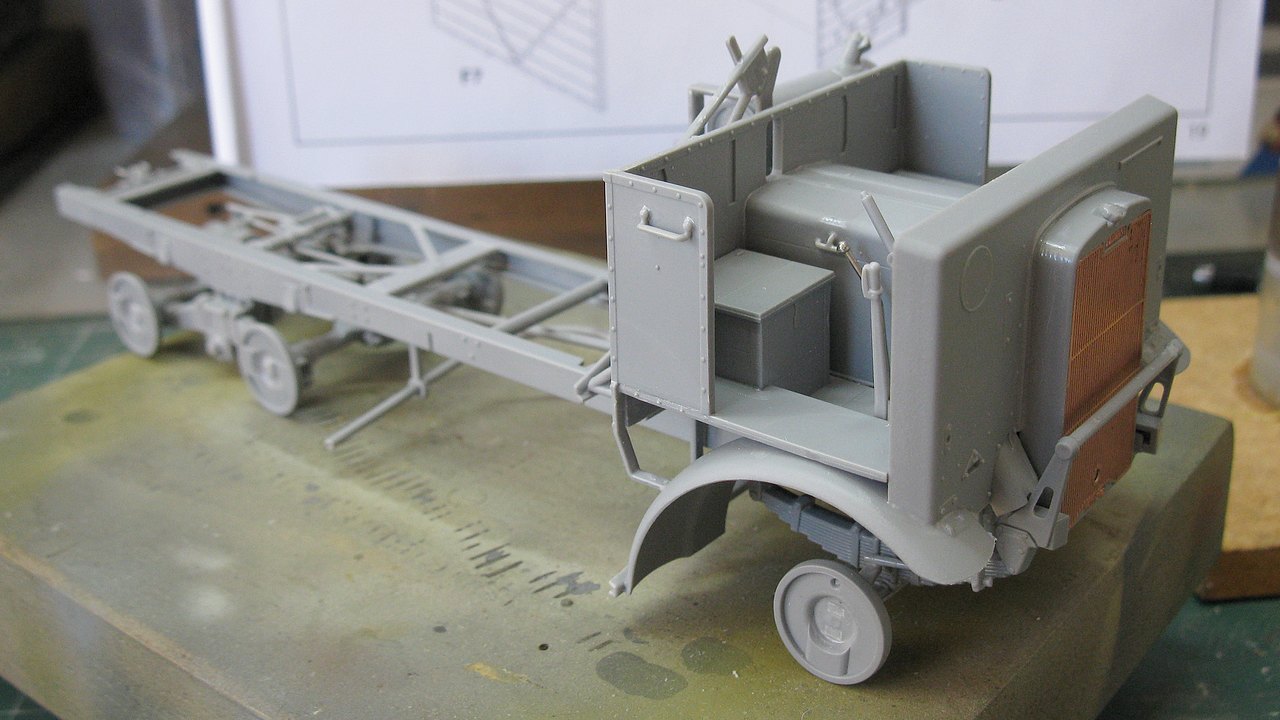
Here, I made a variation in the building sequence: I decided to build the front axle before the rear ones, to allow a perfect alignment between the axles, wheels and the chassis. Here is my recipe: build the front axle and place all parts in perpendicularity, so that there are no deviations in the construction of these parts....
 |
Front axle: wheels in perpendicularity.
Notice that the inner parts of the wheels are in contact with the jigs ... |
While the glue on the front axle dries, I will do the same with the rear axles. But now, we have a problem: the rear axle tips are a little long, "pointing" out from the inner parts of the wheels, preventing me from using the inner part of the wheels as a flat face to be supported on the perpendicular jigs. The logical option here is to cut out these small pointed projections (red arrows, below), which do not interfere with gluing, but interfere with alignment. See the photos below:
 |
Notice the projections of the rear axle, pointing out to
inner part of the wheels (see the diagram...).
Lets cut these points... |
 |
Left, the rear axle with surgery done (green arrows)
and right, virgin axle. Notice the points (red arrows) |
 |
The axle point cutted (red arrow). Notice in the
diagram, the inner part of wheel can it can be perfectly adjusted to the
flat part of the template, ensuring the perpendicularity of its position. |
 |
It is now possible to align the axles and wheels to
the perpendicular plane, avoiding distortions ... |
 |
Perfect alignment between wheels and axles !!!
front view. Kojak is a wise guy!!! |
 |
When we glue the rear axles to the spring beams,
we place a small weight on the chassis to keep everything in place ... |
 |
| And the final results of all the alignment work !!! |
 |
When the wheels are glued (after painting ...),
the Brit girl will be all pretty on top of her 6 shoes, stunning !!! |
 |
Belly view: cardan shafts, axles, suspensions,
engine, chassis ... all aligned !! |
 |
| ..and talking about alignement...all perfect!! |
 |
The wheels and tires...
Painting will be much easier ... |
 |
| Building the cabin: notice the gearbox lever replaced by a pin ... |
 |
Dry run of the cabin in top of chassis... Cool!!
I wanted to test how much the cabin "hides" the view of the engine,
so that I can do some details on the "engine clone"... |
 |
Hmm..the engine rear view is awful...
When looking from below, there is an absence of the sides of the engine,
but the space is very narrow ... |
 |
I decided to make the "box" for the side walls of the engine,
but in a very crude way, as the view is minimal ...
I am definitely not a radical "Rivet Counter" !!! |
 |
Sprues and plasticard!!
I can almost hear from here, in the Southern Hemisphere,
a bloodthirsty mob screaming: Heresy !!! |
 |
Testing the "details" with the cabin ...
The whole thing will be very closed by the cabin and the radiator.
I'm really cool with this.... |
 |
But the rear portion of the transmission is visible and scary ...
I'll have to fix it ... |
 |
In return, the radiator was a little gem !!
I salute you, ICM !!! |
 |
With the radiator in place, the entire engine portion was hidden,
in a normal angle of view ...
A little relief for this heretical modelist !!! |
 |
Cabin with spare wheel rack
and fuel tank... |
 |
Cabin with spare wheel rack and fuel tank: rear view
The flat portion is still very visible,,,hmmmmm |
 |
I added volume to the transmission, with acrylic "dripped" with brush ...
It looks almost the same, but the volume I got was clear ...
I'm satisfied, for now. Let's see with cargo bay in position ... |
 |
A view of the "clone engine", from its lower portion.
As you can see, the thing was satisfactory (IMHO)
There is very little space to see ...
I think "saving" the engine was worth it !! |
 |
And speaking about the cargo area, let's build the body.
There is controversy about the dimensions of this area, but this kit is
being a quick OOTB project. Nothing to complicate things here ... |
 |
The parts fit together wonderfully ...
This kit is being a real delight to build !!!
The best ICM so far in this regard !!! |
 |
| Rear fenders... |
 |
| Tool boxes and fenders in position... |
 |
Putting it all together...
The cargo area is in dry-run... |
 |
| Right view... |
 |
| The big left footboard... |
 |
| The right one... |
 |
| The canvas arches ... very fragile ... |
 |
| Testing...testing... |
 |
Do you remember the infamous and scandalous heresy ??
It doesn't seem to be that big now ... |
 |
| Really, not so big... |
 |
With the spare wheel in position,
I would say almost imperceptible ... |
 |
On the other hand, my truck may be carrying a spare engine,
in its cargo area .... With all its details in sight ...
just build a wooden cradle and voiláaa !!
I think with that, I redeem myself a little from being unorthodox !! |
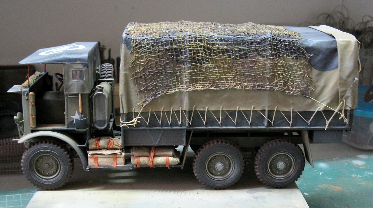
But one thing that is really bothering and worrying me, is the fragility of the arcs that support the canvas, in this kit. As I said at the beginning of this article, this kit is commission work and my client lives 1,400 km away. And the courier employees are always careful and sweet with our orders !!!
 |
| Man, these arches are very fragile and weak... |
Replacing the structural arches with something a little stronger ... Since I am in the field of heresies in this kit, a little more will not hurt anyone ... and after coated with canvas, the arches practically disappear ... .
 |
My solution: another heresy!!
Arches made with copper wires...Much stronger !!! |
 |
| Dry-run of the all parts togheter... |
 |
| Testing the canvas of the cabin... |
And as the next step will be painting, let's go to historical research: and I think you must have noticed the spoyler in the pin up image at the beginning of the article. Our girl is providing services in the famous
Operation Market Garden, September 1944, in the Netherlands, together with the
3rd Infantry Division (Ironsides), with Towed Field Batteries Artillery, as the number 2 ammunition and cargo carrier truck, along with the 1st Battery. The girl will proudly wear a Mickey Mouse camouflage!!
 |
| First of all, primer!! |
 |
| Shades of green and Mickey Mouse cammo |
 |
| Side view... |
 |
| Rear view... Next step: markings!!! |
Decal time: best part!!
 |
| Front and rear view: Ironsides!!!! |
 |
A very big allied star of aerial reconnaissance...
Nothing like having aerial superiority in these times... |
 |
| Decals and painting in the dashboard...see below... |
 |
| Leyland Retriever dashboard |
First of all: when gluing the canvas to the model, leave a "tab" (mooring zone) without glue, so you can pass the binding threads... If the canvas is fully glued in this area, your thread will tear the canvas when trying to pass through the canvas ... The function of the threads is only aesthetic... they are not the ones that keep the canvas in place.
 |
Step 1: noticee that the canvas is glued to the side walls above the
so-called "mooring zone". This portion of canvas must NOT be glued to it...
THIS IS VERY IMPORTANT... |
Step 2: Cut a long piece of khaki polyester thread to make ALL the mooring on one side. Start by the tie ring, tie a knot and apply a microdrop of cyanoacrylate at the knot-metal junction. Insert the thread into a fine sewing needle. It is with this needle that you will pass the thread through the mooring rings and, more importantly, transfix the canvas, making what would be the mooring eyes on the canvas.
 |
The first knot of mooring.
After the knot was made, attach the thread to the needle... |
Step 3: Pierce the canvas very carefully, at the desired height, keeping the needle as tangent as possible to the side walls of the body, avoiding tearing the paper. Use tweezers to help with this step. I do not recommend threading the needle and at the same time threading the next mooring ring. This usually tears the paper... The ideal is to pass the needle through the canvas, pull the thread carefully and, in a second step, pass the needle through the mooring ring. No laziness or shortcuts at this time!!!
 |
Piercing the canvas...
Notice the tangent position of the needle... |
 |
| After passing through the canvas, we will pass through the mooring ring... |
Step 4: An important detail is that you keep the thread in tension (but gently, to avoid the thread "cutting" the canvas...). With the thread tensioned, you can apply a micro-drop of cyanoacrylate in the holes in the canvas and in the tying rings, to keep the whole tying well stretched and tense, without any danger to the paper or to the aesthetics.
 |
Work methodically and in stages...
It may sound complicated, but it's not... |
 |
It is very important to keep the thread tensioned.
When moving from one mooring ring to another, the micro drop of cyanoacrylate
holds everything in position...Now, just repeat the procedure until the end. |
Final step: Plan the final tie-up, always taking into consideration the logic of the thing... Then, just repeat the procedure on the other side... The results are usually very good...
 |
| Now, just repeat the procedure, until the final mooring... |
 |
| The recipe for leather strips... |
 |
After drying, with the scalpel and metal ruler, I cut the strips and
in the grooves of the cuts, I apply a wash effect with oil paint... |
 |
| After that, I do a discreet dry-brush, to highlight the texture of the tapes... |
 |
...and the strips are ready to be glued into place.
Don't trust the adhesive on the tapes: use cyanoacrylate...
Glue the ends of the tapes in the right places, first... |
 |
The other side...Notice the logical positioning of the straps...
Some are extensions of the existing ones... others, totally new... |
 |
The strips, positioned and glued. The buckles do not appear,
as they are under the existing roll-bags...
And the "extended" ones already have their buckles... |
 |
| Note the extended tapes on the right side... |
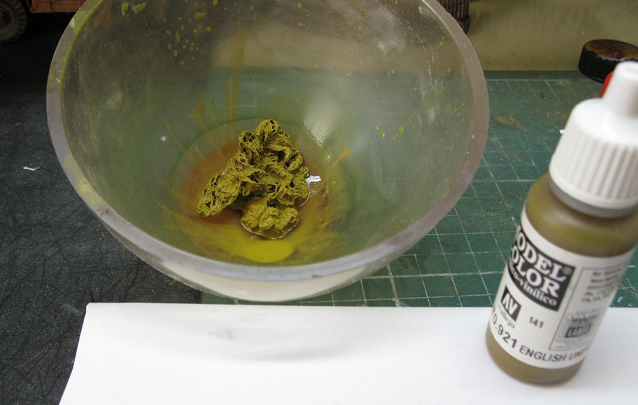
My client asked if I could make a camouflage net over the canvas... Let's try to do something...As I'm an oral surgeon, let's use my everyday materials: surgical gauze!!
 |
| Good quality surgical gauze without being too "hairy" |
 |
I'm going to make two types of cammo nets; a larger one for the canvas
and a smaller one for the cabin. Here is the cabin version, in green only...
Dilute acrylic paint in water only... and let it soak for about 5 minutes... |
 |
The larger cargo bodt version. I'm going to use a greenish khaki
shade for this camouflage net... |
 |
Note the polyester thread passed on each side of the gauze.
The net laid out on a flat surface to dry the primary dye... |
 |
| After the basic color has dried, I make some strips in black, with the airbrush... |
 |
Then, I apply by "brush strokes" small patches of light green,
in the lighter areas of the net... |
 |
And I repeat the same process, this time with red-brown, in the darker areas...
You may have noticed that I am ecumenical with my paint manufacturers...
Tamiya, Vallejo, Andrea, AK...
The important thing is that they are good and available... |
 |
Tying the camouflage net onto the canvas, using the mooring rings...
|
Once the cammo net tied, I apply with a soft wide brush a solution of 50% PVA glue and water. Notice the "shiny" aspect of this solution on the upper portion of the canvas. This will be eliminated with the subsequent application of the matte varnish...
 |
The 50% PVA glue and water solution serves to adhere the net to the canvas...
and prevent the net don't look like fluff... |
 |
| The cabin's cammo net, Carefully rolled up with the aid of PVA glue |
 |
Oops…I was forgetting the canvas cabin tensioning straps.
Passing the strap through the mooring rings... |
 |
And after gluing with cyanoacrylate, fold the ends.
Later, I will paint these areas light brown. And I'm going to make
the buckles with little pieces of plastic rods 0.6mm in diameter. |
 |
Ready-made tension strips as well as containment strips
in light green net. Notice the "buckles"...
The manual start crank also in position... |
 |
| With the nets in position... |
 |
| The girl was very sexy dressed in these nets... |
 |
| Left view... |
 |
Right view.
Notice that the glossy appearance of the PVA glue disappeared
from the canvas after applying the matte varnish... |
 |
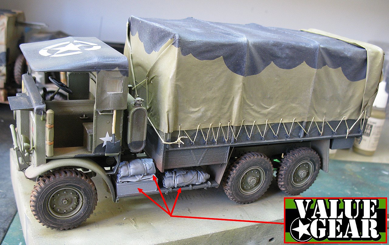
Adding new details: helmet, Lee Enfield .303 rifle
jerry-can and rope for the manual start crank... |
 |
| ...and a few more roll-bags in the cargo area...After all, details never hurt... |
 |
| Time to give to our girl some light!! Headlights first... |
 |
Then the transparent headlight lenses and the
small positioning side lights... |
And my Brit lorry was done. I am pleased to introduce Leyland Retriever - GS version, with markings of
3rd Infantry Division (Ironsides), with Towed Field Batteries Artillery, as the number 2 ammunition and cargo carrier truck, along with the 1st Battery, performing duties in the famous
Operation Market Garden, September 1944, in the Netherlands. This 3 ton girl vainly wear the Mickey Mouse camouflage.
 |
Leyland Retriever - GS version, - 6x4 3 ton
left view |
 |
Leyland Retriever - GS version, - 6x4 3 ton
3/4 rear left view |
 |
Leyland Retriever - GS version, - 6x4 3 ton
cargo area view |
 |
Leyland Retriever - GS version, - 6x4 3 ton
3/4 rear right view |
 |
Leyland Retriever - GS version, - 6x4 3 ton
right view |
 |
Leyland Retriever - GS version, - 6x4 3 ton
|
 |
Leyland Retriever - GS version, - 6x4 3 ton
3/4 front right view |
 |
Leyland Retriever - GS version, - 6x4 3 ton
front view |
 |
Leyland Retriever - GS version, - 6x4 3 ton
with Kojak and Rover, the dog. |
 |
| Two Leyland Retriever girls, side by side... |
Thanks for follow us, Lads!!
New projects, soon!!


