Fellow modelers!!!
The subject of this article is about the use of a weapon as old as humanity itself: about the use of fire as a weapon. Let's get to know one of the many prototypes devised by Man to use fire as a means of killing and intimidation. Based on the horrifying experiences lived by combatants in the Japanese islands of the Pacific, the T33 Mechanized flamethrower was developed to be a decisive weapon to be used in the planned Invasion of the Japanese metropolitan Islands, but the end of the War in the Pacific limited its production to only 3 prototypes.
Today we are going to meet the T33 - M4A3E2 mechanized flamethrower tank.
 |
T33 - M4A3E2 (HVSS) mechanized flamethrower tank
Prototype number 3 - USA 3083021 |
History:
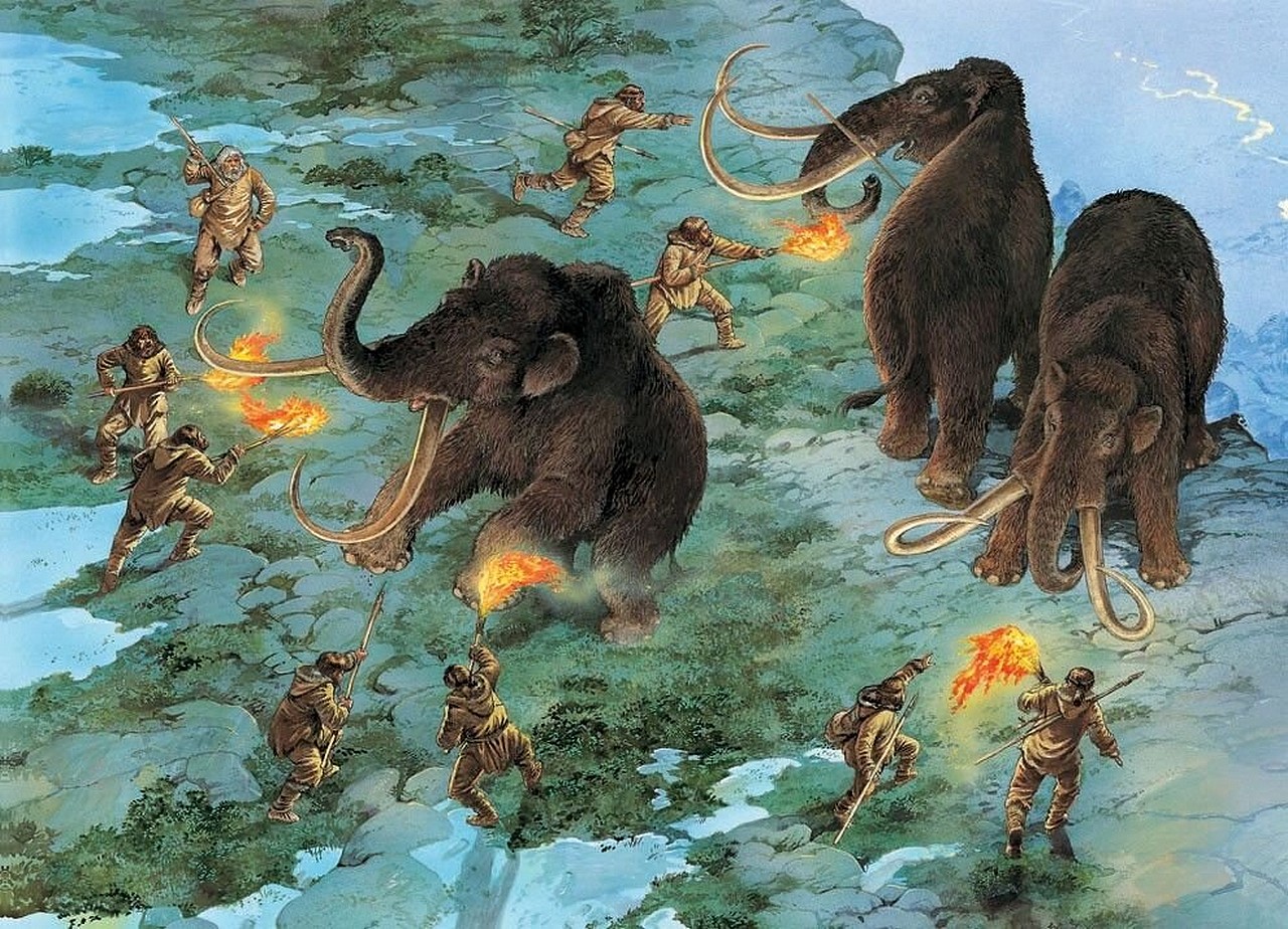
Fire has been used as a weapon since the dawn of mankind, but the so-called modern flamethrower only appeared on the scene of armed conflicts in the WWI.
 |
Cavemen using torches of fire, leading a herd of mammoths to leap
to their death from a cliff. The use of fire as a weapon really is very old... |
And within that context, the US Army has always been very skeptical about the real operational value of this type of weapon, and even slower to recognize the tactical utility of a vehicle carrying a forward combat flamethrowers.
 |
German troops try to fend the attack of a British tank Mark IV Female
with portable infantry flamethrower.
Near River Somme, probably August 1918 - Battle of Amiens |
In the specific American case, this only started to change around 1943, when the experiences arising from the merciless fighting against the Japanese in the Pacific Theater of Operations were interpreted and assimilated.
 |
at a Japanese fortification as another soldier covers him with a rifle. Official caption on front: "Flame thrower team blast Jap position. |
When the geographic focus of the fighting in the Pacific shifted in 1944 from the tropical jungle environments of the South Pacific to the coral and volcanic islands of the Central Pacific, the requirement for an armored vehicle carrying a flamethrower, preferably a tank, became more pressing. The Japanese tactics of battles of attrition, with the use of fortifications and underground caverns, indicated to the Americans that the flamethrower was the most effective weapon in combating these fortifications and in expelling or eliminating the enemies.
 |
A Marine flamethrower tank based on the M4 Sherman pours a stream of fire
through openings in Japanese underground entrenchments near
the city of Naha, Okinawa, in 1945. |
The use by the Americans of flamethrowers in the European Theater of Operations (ETO), both infantry portable and mechanized, was much lower than in the Pacific.
 |
American soldiers with M2 flame throwers training
in England, before D-Day Invasion - 1944 |
 |
Art of an American M4 flametrhrower Crocodile tank in action in the Battle for Jülich |
Flamethrower tanks:
A flame tank (or mechanized
flamethrower) is a type of tank equipped with a flamethrower, most commonly used to supplement
combined arms attacks against fortifications, confined spaces, or other obstacles. The type only reached significant use in the Second World War, during which the United States, Soviet Union, Germany, Italy, Japan, and the United Kingdom (including members of the British Commonwealth) all produced flamethrower-equipped tanks.
Taking the Germans as an example, we can describe many of production methods used. The flamethrowers used on the vehicles could be the existing but modified versions of the portable flamethrowers used by the infantry, like Flammpanzer I or the specially designed flamethrowers such as the Flammpanzers II and III, plus the flamethrower Stugs and Hetzers. Captured vehicles could also be transformed. The French car Char B1 bis is an example.
The flame guns were usually externally mounted as on the Flammpanzer II Flamingo or replaced existing machine gun stations or even the tank's main armament, as on the Flammpanzer III. Fuel for the flame guns was either carried inside the tank, in armoured external storage, or in some cases in a special trailer behind the tank, as in the case of the British
Churchill Mk.VII Crocodile.
The maximum range of a mechanized flamethrower was typically less than 150 metres. Because of this limitation, the flamethrower was virtually useless on an open battlefield. However, they proved a potent psychological weapon against fortified troops. In many instances, troops surrendered or fled upon seeing a flame tank fire ranging shots, rather than risk being burned alive. On the other hand, the crews of these tanks were usually eliminated when captured, such was the psychological pressure exerted by this type of weapon.
The T33 - M4A3E2 (HVSS) mechanized flamethrower tank:
As we saw earlier, the combat conditions in the Pacific Theater of Operations showed the value of the flamethrower as a weapon, as well as the extreme vulnerability of its operators, who had to get too close to their targets to be effective.
 |
A US Marine employing his M2 flamethrower in a virtually
point-blank range situation, pouring a stream of ignited napalm
through the opening of a Japanese pillbox on the slopes of a hill in Okinawa.
His only defense is his colleague at his side, carrying a .30 M1 Garand
for close combat. The losses among the flamethrower operators were very high. |
To correct this serious tactical deficiency, the Americans tried several experiments, with flamethrowers fitted in specially modified lights M3 or M5 tanks and in M4 medium tanks. The flame projectors were first installed in the position of the machine gun of the frontal armor. Later in the place of the main gun and finally, in the M4 Shermans, in a position coaxial to the main gun, maintaining its standard military capacity unchanged.
 |
M3A1 Satan flamethrower tank with his flame projector installed in
the frontal hull machine gun station, pouring out a jet of ignited napalm.
New Caledonia - October, 1943. |
 |
A M3 Satan flamethrower tank attacking with a jet
of glowing napal a Japanese stronghold on Saipan.
Notice that the flames are ejected by the projector installed
in the main weapon station.
June - 1944. |
 |
M4 Sherman flame tank belonging to709th Tank Battalion,
near Zweifall, Germany. 24 November, 1944.
The flame projector is the hull version. Notice the primitive
hedgerow cutting device welded in the transmission cover. |
 |
M4A3R3 flamethrower tank from 713 Tank Battalion,
C Company, burning holes conected with Japanese HQ, in Hill 95.
Okinawa - 22 June, 1945.
Notice the use of the main gun station for the flame projector. |
 |
Two M4A3R3 flamethrower tanks attacking Shuri line
Okinawa, 1945
Notice the flame projectors in the main gun positions. |
 |
A M4A1 (VVSS - 75mm) POA-CWS-H1 prototype flamethrower tank
at Fort Leonard Wood, Missouri - USA.
Notice the flame projector installed on the right side of mantlet,
next to the main gun, which continued to be operational. |
%20105mm%20as%20POA-CWS-h5%20flamethrower%20tank%20in%20tests%20in%20Hawaii%20-%20July,%201945.jpg) |
A M4A3E8 (HVSS - 105mm) POA-CWS-H5
during tests in Hawaii, in July - 1945.
Some were even sent to the Pacific, but did not arrive
in time to participate in the fighting. |
%20105mm%20as%20POA-CWS-h5%20flamethrower%20tank%20in%20tests%20in%20Hawaii%20-%20april,%201945.jpg) |
Four M4A3E8 (HVSS - 76 mm) POA-CWS-H5 in firing
tests in Hawaii, with tickened napalm, in 26 April, 1945.
Notice the big firing range of the flame projector. |
T33 - M4A3E2 (HVSS) mechanized flamethrower tank:
A new development contract was signed in May 1945. The POA-CWS type projector (with new E20-20 flame pistol) was chosen, installed in a new casted turret, with a 75mm axial cannon installed in independent mantlets. This turret was installed on the most armored version of the Sherman hull, the M4A3E2 version (Jumbo type), but with the new HVSS suspension, which better distributes the weight of the extra armor in relation to the ground. This version has been designated by the Ordnance Committee as the T33 - M4A3E2 (HVSS) mechanized flamethrower tank.
 |
| Artistic conception of the new T33 flamethrower tank |
To save the always restricted space in the turret, the 75mm gun was the M6 version, characterized by its concentric recoil system, same that used by the M24 Chaffe light tank. As described before, the main gun and flamethrower had separate mantlets but shared the same support. The 75mm cannon was on the left mantlet, with its coaxial .30 machine gun installed to the right of the gun. Ammo for the 75mm was 40 rounds.
 |
| Position of armament in the turret of the M24 Chaffee light tank |
An auxiliary M3-4-E6R3 periscope flamethrower gun was originally specified for mounting in the periscope of the tank commander's vision cupola hatch. It could be traversed approximately 240 degrees, providing close-in protection.
Two fuel tanks in the lower hull and two in the turret provided a net capacity of about 950 liters for use by both flame guns.
The T33's crew was originally designed to be five men, with the tank commander situated in the center and aft portion of the turret. On the roof of the turret, in front of the commander's 360° vision cupola, were two oval hatches: one for the gunner and the other for the loader. Later, the crew was reduced to 4 men, with the elimination of the hull machine gun station.
The E20 main flame gun had an elevation of +45º to -15º, but the 75mm gun only reached +13º to -10º. The original build plans called for the acquisition of 20 T33s in an initial shipment, with the possible production of an additional 600 tanks. With the advent of Japan's surrender, the order was limited to just the three pilot models, all converted from M4A3E2 hulls with HVSS suspensions. These vehicles were identified as follows:
- Tank pilot nº1 - USA 3082940
- Tank pilot nº2 - USA 3083011
- Tank pilot nº3 - USA 3083021
With the end of the war, work on the pilot vehicles proceeded much more slowly and the first tank was delivered to Aberdeen only in September 1947. The second and third tanks arrived in January 1948. All tests were carried out in Aberdeen, but no others additional vehicles was produced, with the series being limited to the 3 tanks initially produced.
 |
| The three pilot tanks produced. |
The T33 story does not end with the pilot vehicles being tested in Aberdeen. Influenced by the
Badger canadian flamethrower tank battle history, two of the T33s pilots were converted in 1953 to the T68 M4A3E2 (HVSS) mechanized flamethrower tank.
With conceptual lines very similar to the Canadian vehicle, the tanks that were used in this experiment were the USA 3082940 (Pilot nº 1) and USA 3083021 (Pilot nº 3).
 |
T68 M4A3E2 (HVSS) mechanized flamethrower tank
derived from T33 tank pilot nº3 - USA 3083021
3/4 front left view
Aberdeen - 1953 |
 |
T68 M4A3E2 (HVSS) mechanized flamethrower tank
derived from T33 tank pilot nº3 - USA 3083021
3/4 rear left view
Aberdeen - 1953
|
The main characteristics were that the tanks had their turrets removed and replaced by a soft steel cover, equipped with a 360º dome. of sight and a support of .50 caliber machine gun. A canadian flame gun (Iroquois, designated E33) was installed in the forward hull machine gun position. The vehicle carried three crew members (commander, driver and flamethrower operator) and 830 liters of fuel for the flame gun. Thus configured, the T68 was tested in Aberdeen from 18 November to 11 December 1953, and they were not recommended for series production.
Specs:
| M4A3E2 (HVSS) T33 flamethrower tank |
|---|
| Type | Flamethrower tank |
|---|
| Place of origin | United States |
|---|
|
| In service | trials only |
|---|
| Used by | United States (trials only) |
|---|
| Wars | |
|---|
| Designer | U.S. Army Ordnance
Department |
|---|
| Designed | 1945 (late) |
|---|
| No. built | 3 prototypes |
|---|
|
| Mass | 38.1 tonnes |
|---|
| Length | 6,27 m |
|---|
| Width | 3,00 m |
|---|
| Height | 3,18 m |
|---|
| Crew | 4 (commander, gunner,
loader, driver) |
|---|
|
| Armor | 12.7 to 177.8 mm |
|---|
Main armament | E20-20 flamethrower
(+45°, -15°) |
|---|
Sec. .armament | 75mm M6 gun (40 rds.)
E6R3 flame gun (cupola perisc.)
30 caliber Browning M1919A4 coaxial mg
(3.000 rounds)
.50 caliber Browning M2HB mg (Comm. turret)
(300 rounds)
|
|---|
| Engine | Ford GAA V8 gasoline engine; 450 hp (336 kW) @ 2,600 rpm |
|---|
| Power/weight | 11,8 hp / short ton |
|---|
| Transmission | Spicer manual
synchromesh
transmission
5 frw. x 1 rev. |
|---|
| Suspension | Horizontal volute spring suspension (HVSS) |
|---|
| Fuel capacity | 605 liters |
|---|
Operational range | 161 km |
|---|
| 35 Km/h on road |
|---|
The kits: A problem arose: there is no kit on the market with the M4A3E2 hull with horizontal volute suspension (HVSS). The option is to transform what exists...
Either we take an M4A3E2 Jumbo hull and adapt an HVSS suspension in the lower portion of the hull or we take an M4A3E8 hull (which has the HVSS suspension) and reinforce the front and side armor plates, in addition to doing the same "surgery" in the transmission cover. This last option was chosen by me (and by Kojak...).
...and for the turret, the fantastic resin kit from
StahlHelmModels:
Sherman T33 flame thrower turret (#35022) |
StahlHelmModels Sherman T33 flame thrower turret (#35022)
Conversion kit for M4A3E8 1/35 kit |
 |
Kojak, undaunted, facing the new challenge ahead:
transforming an Easy Eight into a Jumbo with wide feet!!!
Let's go!!! |
I' started by the conversion kit, the turret.
StahlHelmModels resin pieces are simply fantastic!!! Follow the work...
 |
| The quality of the casting is incredible... A delight to work with... |
 |
The fit between the two turret halves is smooth...
The dimensional imperfections between them will be easily
removed with Dremel abrasive points... |
 |
Starting to glue the parts with methyl cyanoacrylate (superglue)...
Really, this was the best invention in the world, after Coca Cola!!! |
 |
Once the halves are perfectly glued, we'll trim off the
excess with Dremel abrasive tips... |
 |
| A quick, rough but effective job... |
 |
| Larger portions removed (mercilessly...) with the abrasive tips... |
 |
Now, let's improve the adaptation with tungsten dental cutting drills,
which promote a clean cut without generating excessive heat...
A real party !! |
 |
Dosing the speed, we managed to remove the resin with a
smooth finish and without excessive roughness... |
 |
The fine tip of the bit allows us to work in the narrowest of corners,
without losing effectiveness and saving hours of manual sanding...
Kojak is a wise guy!!! |
 |
The crevices and small depressions in the joint area
being filled with putty... |
 |
| No economy of putty at this stage... |
 |
| The goal is to regularize and not completely smooth. |
 |
And after sanding, the (small...) irregularities
that remain are even welcome... |
 |
| A nice job to do... |
 |
| This flamethrower turret is very, very cool!!! |
Well... while the work on the turret rests between the drying layers of putty, let's take care of the Tasca's hull. The turret ring hole is very large in the hull. Time to resize it with some 1.5mm thick plasticard, cut with a cutter compass.
 |
Grinding the turret hole diameter: 1.5mm plasticard cut
and glued to the top of the hull. |
 |
Testing the turret in the new hole, so that everything is perfect...
Notice the layer of putty (yellowish) diluted in acetone applied with a
brush on the surface of the turret, to reproduce the irregularities of the casting |
 |
| Internal view of the rectifier ring, with the turret resting in place.... |
And since we are working with plasticard, let's make the armor reinforcements, typical of the M4A3E2 Jumbo version with 2mm thick plasticard plates...
 |
Additional side armour plates cut from 2mm thick plasticard...
An Easy Eight turning into a Jumbo!!! |
 |
Additional side armour glued in place...
right view |
 |
Additional side armour glued in place...
left view |
 |
| The front armour in place... |
Now it's time for the hardest part: reinforcing the transmission cover. I cut and glued a 2mm plastic plate on the front portion of the transmission cover and waited for it to dry... Before that, I softened the plastic in boiling water to allow the (thick) plastic to adapt to the curves of the cover.
 |
Starting to reinforce the transmission cover. Notice the big hole I made in the
plastic to allow work on the most difficult parts... I used welder glue in this step... |
 |
Don't worry about the rough appearance of the parts...
they will be thinned out in the next steps, when other plastic parts join the set... |
 |
| Side view |
Now, the front portion: I glued a 2mm plasticard piece in the recess of the hole and completed the missing portions with dental acrylic, applying the brush technique: I put liquid and powder acrylic in two separate containers...with the bristles of the brush with liquid acrylic I touch the powder with this wet brush, which captures a portion of the powder...I apply this solution in layers in the desired space. Using this technique, I manage to deposit the material at the same time as I sculpt this fill...
 |
Dental acrylic being applied in layers, using the wet brush technique.
Filling in the gaps between the plasticard boards... |
 |
The transmission cover, with the layers of plastic and acrylic
applied but still unfinished... |
An important detail in this technique is not to apply the acrylic in excess. After its chemical hardening reaction, it is much harder than plastic. You can only wear down acrylic with Dremel abrasive or sharp edges. Manual sandpaper no way!!! Notice the image below:
 |
| Adapting details from the Tasca kit to the reinforced front cover... |
 |
Kojak really is a creative guy (and practical...
this all took about 30 minutes to finish...) |
While we rest from the emotions of the additional shields, let's move on to the simple construction of the hull bathtub... No difficulties here: the kits Tasca (Asuka) are simply superb!!!
 |
| Let's build the hull bathtub... No problems here!!! |
 |
| Drive sprockets and idlers... |
 |
The turret is a show apart. Detail: I added some "production" details
on the roof of the tower. My kit would be a production version, let's say.
And an armored fan in the turret,s roof is mandatory in a three-man tower...
|
 |
The details of the Tasca/Asuka kit and some metal wires
make all the difference...
The machined aluminum barrel is part of the conversion kit |
 |
A tedious step, but important to be done very well: the suspensions...
and the HVSS system has many, many wheels... |
 |
HVSS bogies perfectly built and aligned.
I don't want my girl to have crooked feet.... |
 |
| Now, we have a M4A3E2 hull with HVSS suspensions... |
 |
Our girl was very fashionable: Jumbo body with Easy-eight feet!!!
Notice the glacis machine gun station closed with an armored plate and
the layer of diluted (yellowed) putty on the transmission cover. |
 |
Upper view of the hull.
Notice the fittings on the hull tower ring
(which I made by cutting the plastic...)
|
 |
The turret, fully built. Notice the antennae, made with acupuncture needles...
Unfortunately, the mantlets are not mobile. I scaled the two weapons
according to my aesthetic criterion, such as for mid-distance fire
(either by projectiles or by fire...).
The left rack position would be a possibility in production vehicles...
Left view |
 |
The turret, fully built. Notice that the rack position would be
a possibility in production vehicles...
Right view |
 |
The turret locking system in the kit.
I'm terrified of loose turrets... |
 |
| The turret rotated 90º, to fit in the hull turret ring fittings... |
 |
| And the turret rotated towards the bow, rotating in the hull fittings... |
 |
Adding side Tasca/Asuka details (dark green) to the tank's hull.
The toolbox (in light gray) on the back of the fender is a spare part from an old Dragon kit.
Left view |
 |
Adding tabs on the rear fenders. The phone box (in medium green)
in the rear right plate is from my scrap box (Academy). |
 |
| Right view |
 |
| 3/4 front right view |
Notice the electric cables in the front glacis
installed between the headlights and penetrating inside the tank
through the hull front ceiling fan. The girl is ready for make-up!!!
While I look for markings for this hypothetical girl (don't forget: I'm building what would be a production line tank, if the war went on for a few more months...), I'm going to paint the whole vehicle with Vallejo olive-drab primer.
 |
| Primer Vallejo olive-drab. |
Oops...I was forgetting about the weld marks on the edges of the front and side armor reinforcement plates, typical of the M4A3E2 Jumbos... See below:
 |
| Notice the weld beads between the armor plates, typical of Jumbos |
To make these weld marks, I use a scalpel blade nº15 with the tip cut off, tied ( with copper wires) to the tip of my 40 watt electronic soldering iron. I heat the tool and apply the heated blade to the joint between the plates, melting the plastic, simulating the weld beads of the original vehicle. Simple, fast and efficient...
 |
| The tank hull and the tool!!! |
 |
Notice the complexity of thePanzerserra´s tool to simulate weld beads...
Typical rocket engineering!!! |
 |
The weld beads, on the M4A3E2 armour plates...
right front view |
 |
Larger irregularities will be sanded and then
painted with the base color.
Front view |
 |
The weld beads, on the M4A3E2 armour plates...
left front view
|
 |
| The turret, painted with base color primer. |
 |
The regularization of the base color painting
left view |
 |
The regularization of the base color painting
front right view
|
 |
The regularization of the base color painting
front view
|
 |
Installing the Tasca/Asuka vinyl T66 tracks
They are of very good quality.
Left side |
 |
Installing the Tasca/Asuka vinyl T66 tracks
Right side |
 |
T33 mechanized flamethrower almost ready
Rear view |
As always, I like to make a color guide and markings for my projects whenever possible. This time, I chose what would be a T33 mechanized flamethrower of a possible production line, in late 1945, in a hypothetical invasion in the main islands of Japan.
The markings were taken from my spare decal box...and I couldn't resist using a pretty cowgirl as the pinup godmother of this tank. With you, JANE, a truly hot girl!!!
 |
| JANE really is a hot, a very hot girl!!! |
After a little work with tonal variations on the olive drab of the base color, I applied a thin layer of Pledge (Future) to prevent silvering and, after the Pledge dried, I applied the decals, following the pattern shown above....
 |
| Decals applied and sealed with matte varnish... |
 |
| Our girl is getting really pretty... |
 |
| Left view of JANE... |
 |
| Rear view |
 |
| Right view of JANE |
 |
| Almost ready!!! |
 |
| adding to our hot girl a .50 Browning... |
 |
| ...tools and other stuff. |
 |
| left view |
 |
| rear left view |
 |
| rear right view |
Oooops...I was almost forgetting about the Commander's flamethrower gun. Let's do it from scratch, following the same "cake recipe" that I made on the
T31 Demolition Tank (M4A3E8 HVSS).
But I'm going to sacrifice some historical accuracy here: I'm going to make the base of the flamethrower a little thicker, to avoid accidental breakage. This flamethrower gun is very exposed, here on top of the tank...
 |
| Starting the flamethrower gun... |
 |
Placing the flamethrower gun on the right side of the periscope
of the Commander's cupola hatch |
 |
| The flamethrower gun, in a view from the left side |
 |
Now, let's paint the flamethrower gun with brush
and make the final details, on the kit... |
And with that, I consider this interesting vehicle finished. With you, JANE, a T33 - M4A3E2 (HVSS) mechanized flamethrower tank, with the hypothetical markings of a possible Invasion of the main Japanese Islands.
 |
T33 - M4A3E2 (HVSS) mechanized flamethrower tank "JANE"
|
 |
| T33 - M4A3E2 (HVSS) mechanized flamethrower tank "JANE" |
 |
T33 - M4A3E2 (HVSS) mechanized flamethrower tank "JANE"
left side view |
 |
T33 - M4A3E2 (HVSS) mechanized flamethrower tank "JANE"
rear left side view |
 |
T33 - M4A3E2 (HVSS) mechanized flamethrower tank "JANE"
rear right side view |
 |
T33 - M4A3E2 (HVSS) mechanized flamethrower tank "JANE"
right side view |
 |
Don't get close, because I know how to
defend myself at close range... |
 |
T33 - M4A3E2 (HVSS) mechanized flamethrower tank "JANE"
front right side view |
 |
T33 - M4A3E2 (HVSS) mechanized flamethrower tank "JANE"
with Kojak, very proud of your new girl!!
|
 |
T33 - M4A3E2 (HVSS) mechanized flamethrower tank "JANE" |
 |
| T33 - M4A3E2 (HVSS) mechanized flamethrower tank "JANE" |
Thank you very much for following the entire project, my friends. The conversion kit from StahlHelmModels is really good. See you on the next project!!
 |
| Indeed!!! |


.jpg)
%20Hetzer.jpg)
.jpg)


%20105mm%20as%20POA-CWS-h5%20flamethrower%20tank%20in%20tests%20in%20Hawaii%20-%20July,%201945.jpg)
%20105mm%20as%20POA-CWS-h5%20flamethrower%20tank%20in%20tests%20in%20Hawaii%20-%20april,%201945.jpg)


