
Builders and excavators!!!
Today we are revisit one of those responsible for building the Allied Victory in WWII. Some time ago, we talked about the hydraulic version of this girl... but today, we will talk about the "early and brute" option of this impressive, robust and powerfull machine. Let's meet the Caterpillar D7 Bulldozer with LeTourneau R7 power control unit.

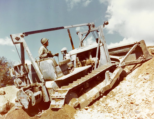 |
| Caterpillar D7 with LeTourneau R7 PCU and LeTourneau WCK7 angledozer moving ground, at the construction Battalion Training Center, Camp Endicott, US Navy. Davisville, Rhode Island - USA - fall of 1943 |
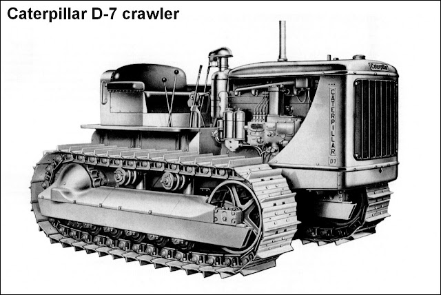 |
| Caterpillar D7 crawler tractor 3/4 front right view |
 |
| Caterpillar D7 crawler tractor 3/4 rear left view |
 |
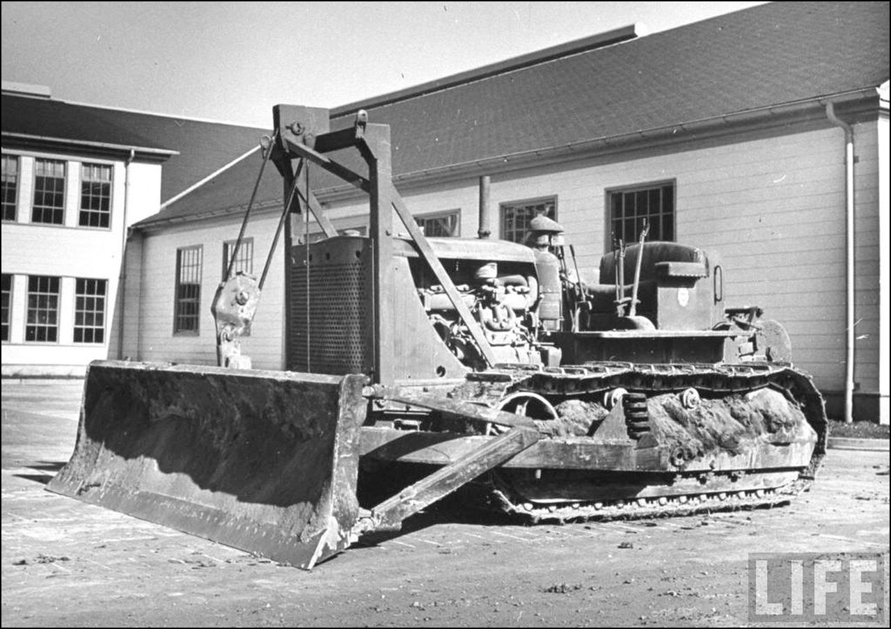
| A commercial Caterpillar D7 (notice DIESEL in the side of the engine hood) under trials with M1 gun 155mm Long Tom, as artillery prime mover. |
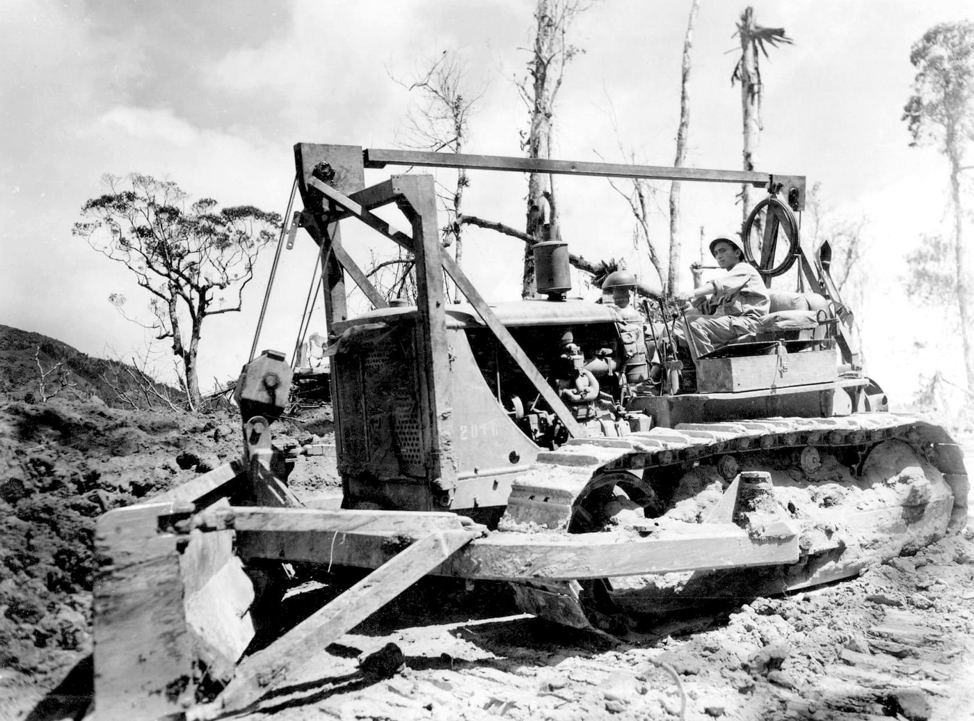 |
| Caterpillar D7 with LeTourneau R7 PCU and LeTourneau WCK7 angledozer from 65th Engineer Combat Battalion, cleaning the terrain in Lynx Red Road Luzon, Philippines - May, 1945. font: Facebook |
 |
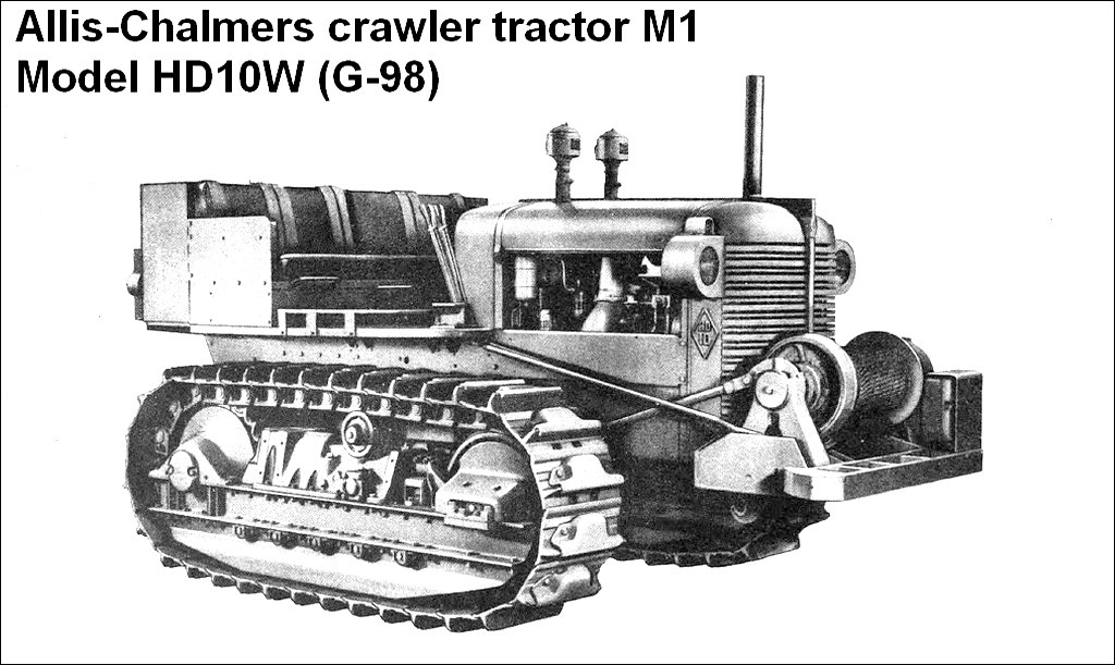
Caterpillar D7 Heavy Tractor, M1 818th Engineer Aviation Battalion France - 1944 |
 |
| Caterpillar D7 dragging medical supplies on a wooden sled at Depot M-402T Carentan, Normandy - 1944. |
 |
| Caterpillar D7 "Booger Kid"with LeTourneau R7 PCU and LeTourneau WCK7 angledozer in a damaged French village, shortly after the Normandy landings. Markings in the rear tractor are 3A - 628E - LE 3rd Army - 628th Light Engineer Company. France - 1944. |
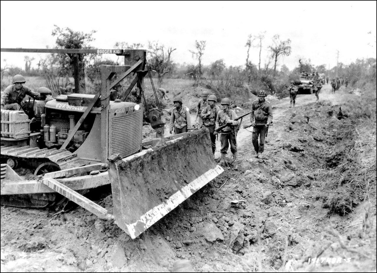 |
| Caterpillar D7 "Booger Kid"with LeTourneau R7 PCU and LeTourneau WCK7 angledozer filling bomb craters on a Normandy country road, west of St. Lo. Notice the right side rack with Germans jerry cansFrance - 1944. |
 |
| The charred remains of the the Panzer IV n.532 being bulldozed by Caterpillar D7 into a heap amongst the rubble. St Gilles, Normandy, France - July 1944 |
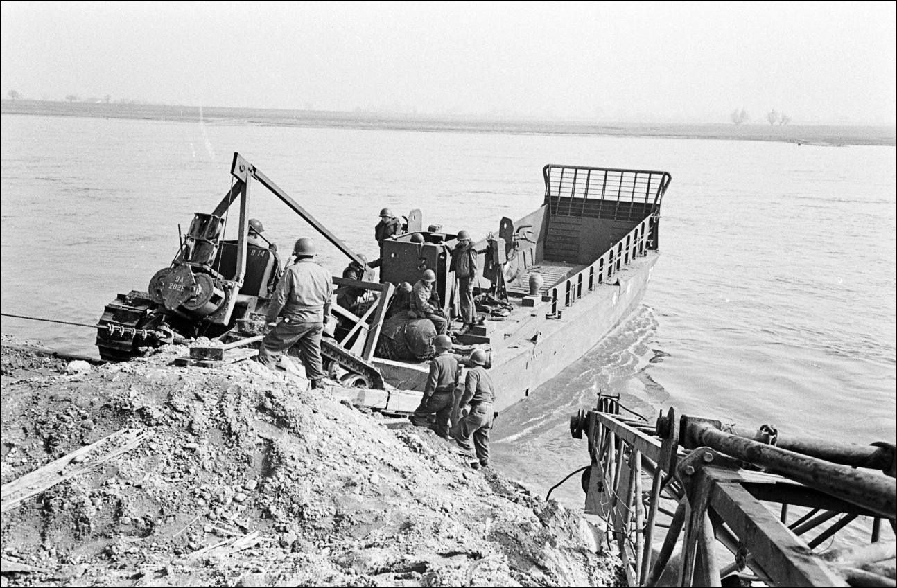 |
| A Caterpillar D7 with LeTourneau R7 PCU and LaPlant-Choate R76R Trailbuilder dozer from US Army gives an LCM(3) a helping push... This photo was taken moments after another photo, a little further down in this article... Operation Plunder - Crossing of the lower Rhine Germany - March, 1945. |
 |
| Caterpillar D7 with LeTourneau R7 PCU and LeTourneau WCK7 angledozer moving ground, at the construction Battalion Training Center, Camp Endicott, US Navy. Davisville, Rhode Island - USA - fall of 1943 |
 |
| Same vehicle and place from the color photo above. The navy blue-gray color pattern is evident on this vehicle |
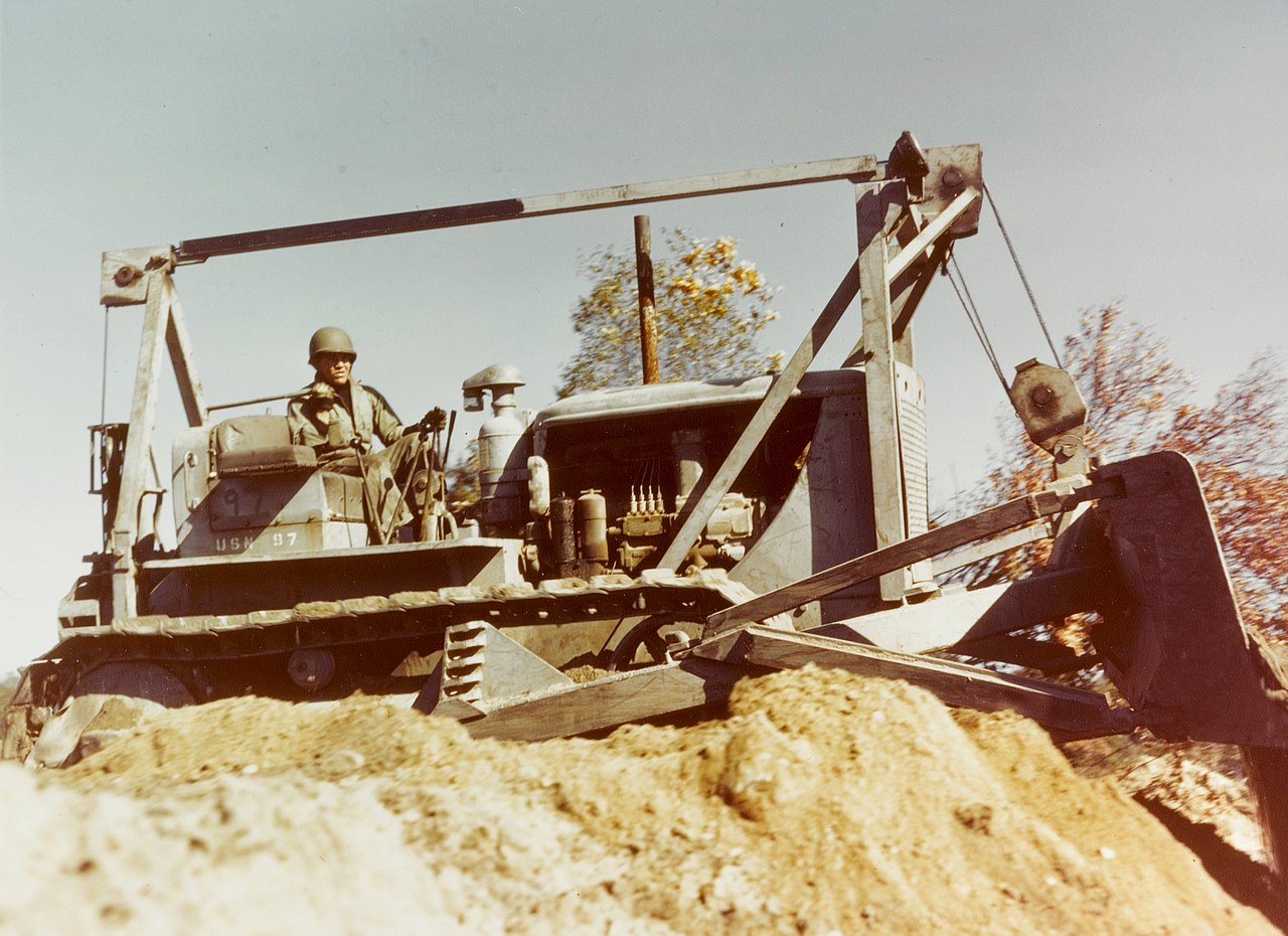 |
| Right side view of Caterpillar D7 from US Navy Construction Battallion tractor Camp Endicott, US Navy. Davisville, Rhode Island - USA - fall of 1943 |
 |
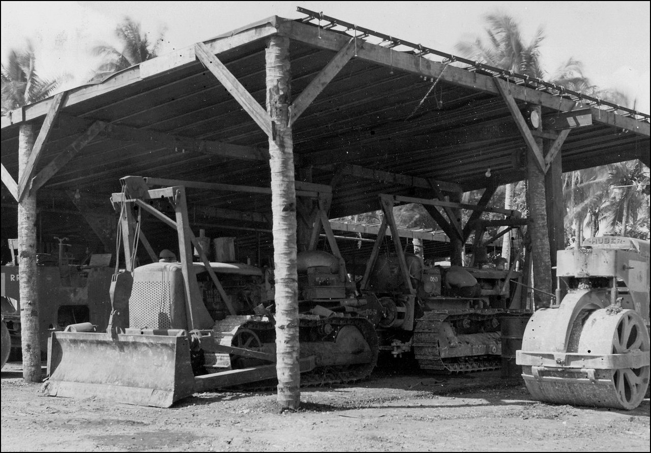
| Caterpillar D7 serving with US Army, cleaning the thick jungle after the Battle of Guam, 1945. |


- D7 7M series, manufactured 1940-1944, approx 10,000 produced. D8800 engine, 74 inch track gauge (1.880mm)
- D7A 1T1001 series, manufactured 1943, 138 produced. Armor plated 7M with twin hydraulic cylinders, rear mounted Hyster D7N winch
- D7 3T series, manufactured 1944-1955, over 28,000 produced
- D7 4T series, manufactured 1944-1945
- D7 6T series, manufactured 1945

.jpg)
- Hyster D7N Towing Winch: It was a robust, single-speed, direct-gear, reversible winch with enough power and strength to utilize the tractor's engine power to pull loads beyond those that could be handled on the tractor's drawbar. The winch must be operated with the tractor stationary.

 |
| Hyster 07N towing winch installed in the rear of a Caterpillar D7 |
 |
| Caterpillar D7 with LeTourneau FTD7 PCU, LeTourneau A7 tiltdozer and Hyster D7N towing winch 77th Combat Engineer Company, 25th Infantry Division Korea War - 1951 |
- LeTourneau FTD7 Power Control Unit: the FTD7 power control unit (PCU) was a single-drum unit mounted in the front of main frame of Caterpillar D7 tractors, below the radiator, for controlling a dozer blade used with the crawler. Could be used in conjunction with a rear mounted cable control unit or a towing winch . This front PCU was driven by the tractor engine. The cable drum of the PCU was connected with the dozer blade up over the sheave of A-frame and down to the dozer blade. By spooling or unspooling the cable on or off the cable drum , the PCU could controls the raising or lowering of the dozer blade. The operator operates the aparatus moving the control lever at the right of the tractor seat.

 |
| LeTourneau FTD7 power control unit installed in front position of Caterpillar D7 tractor see also the cable arrangement and control lever |
 |
| A very dirty Caterpillar D7 with LeTourneau FTD7 PCU, LeTourneau WCK7 Angledozer and Hyster D7N towing winch in the rear |
 |
| Caterpillar D7 of a Naval Construction Battalion (Seabees) with LeTourneau FTD7 PCU to operate the LeTourneau WCK7 Angledozer and a LeTourneau R7 PCU to operate any towed equipment. Eniwetok, Marshalls Group - 1944. |
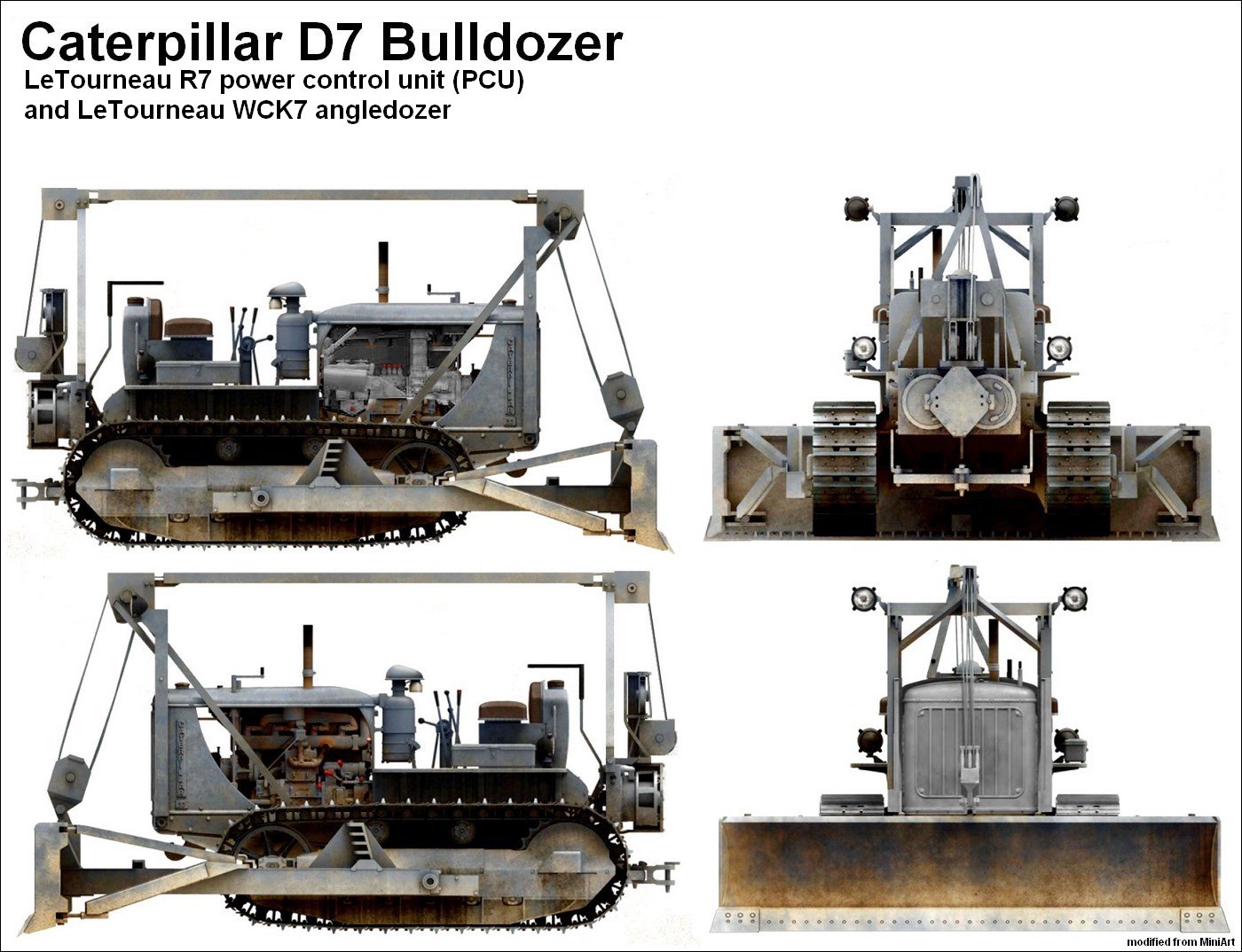
- LeTourneau R7 Power Control Unit: the R7 Power Control Unit (PCU) was a double-drum unit mounted on the rear of the steering-clutch case of Caterpillar D7 tractors to control a wide range of equipment like dozers, scrapers, rooters, cranes etc. A take-off shaft (spline-shaft) connects the PCU with the tractor upper transmission-shaft, and by the tractor engine. Control cables (wire ropes) extend from the cable drums to the equipment that is being operated by the PCU. Two control levers (one for each drum) extend up behind the tractor seat and are within easy reach for the operator. Moving these control levers, the operater can spool or unspool the control cables on or off the cable drums, thereby operating the various working parts of the equipment being operated by the PCU.

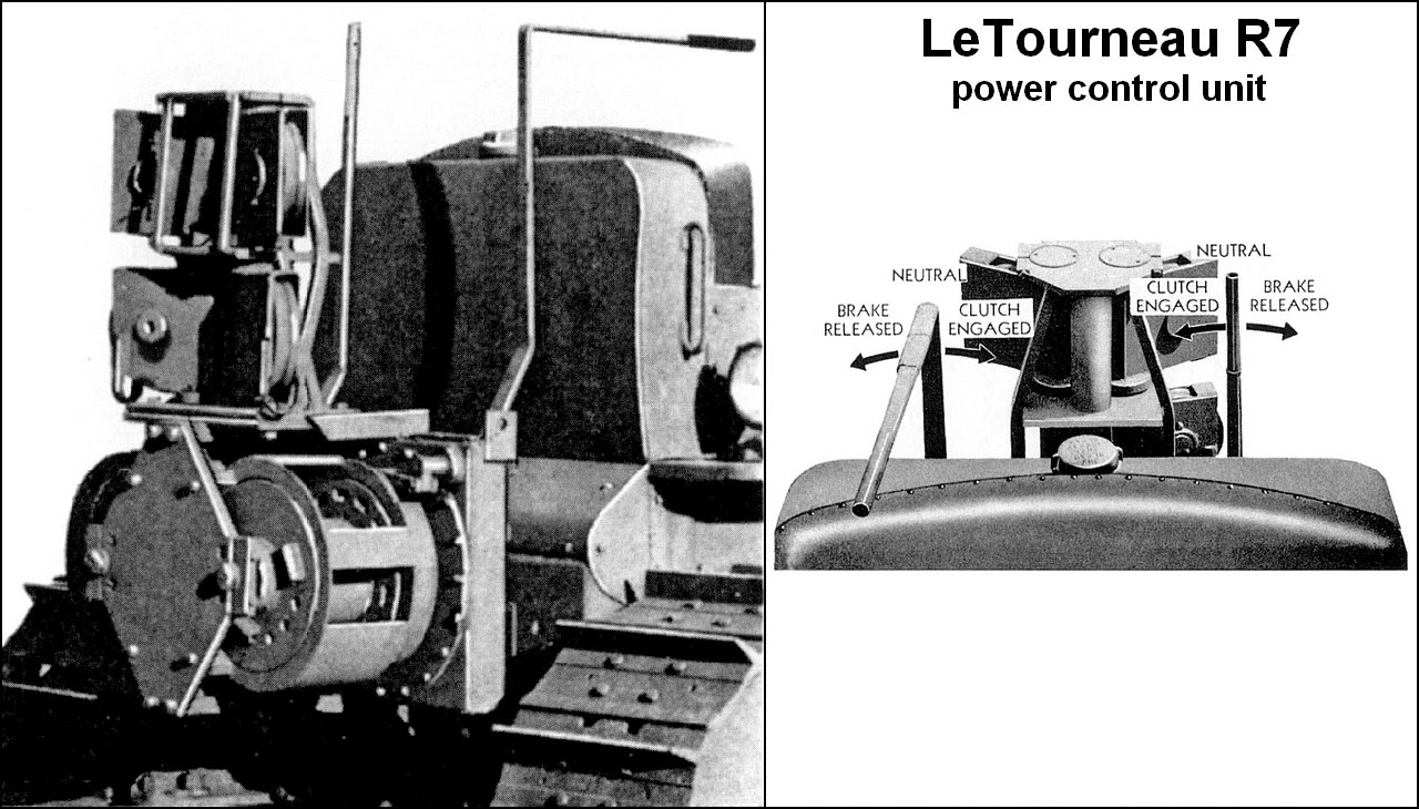 |
| LeTourneau R7 PCU installed in the rear of Caterpillar D7 tractor see also the control levers |
 |
| Caterpillar D7 with LeTourneau R7 PCU and LeTourneau WCK7 Angledozer, removing debris and rubble at Roncey, France. 2, August, 1944. |
 |
| Caterpillar D7 with LeTourneau R7 PCU and LeTourneau XD7 Bulldozer assisting a International Harvester M426 5-ton 4x2 tractor truck out of the mud at an Ordnance Depot. Normandy, France. |
- LeTourneau A7 Tiltdozer: the A7 Tiltdozer consisted mainly of the steel blade or "bowl" across the front of the tractor; the pushbeams, that supported the bowl in front of the tractor; the trunnion brackets, on which the rear of the pushbeams pivots; and the front and rear A-frames and the ridgebeam on which rotated the sheaves over which the cable from the PCU travels to raise and lower the blade. The A7 Tiltdozer could be operated by either LeTourneau front or rear mounted PCUs. The bulldozer required only one cable drum, and when it is operated by a rear-mounted R7 PCU, the spare drum may be used to operate other equipment. By engaging the clutch of the power control unit, the blade will be raised. By releasing the brake, the blade will be lowered. Its design combined features of the bulldozer and the angledozer. The Tiltdozer blade can easily be tilted. The adjustment was performed by the blade tilt adjusting-screws, at the front of each tilting brace. The adjusting mechanism was protected by a curved guard. The sharp pointed end blades are a distinctive feature of the A7 Tiltdozers blades. The A7 Tiltdozer was introduced in 1943 but it is possible that the U.S.Army did not receive any before 1944.

 |
| Cutaway view of LeTourneau A7 Tiltdozer controlled by LeTourneau R7 PCU in a Caterpillar D7 tractor. Notice the pointed sharp ends blade, typical of this blade. |
 |
| Seabee Caterpillar D7 tractor with LeTourneau R7 PCU and LeTourneau A7 tiltdozer. The left curved guard is missing. Salomon Islands - 1945 |
 |
| Caterpillar D7 with LeTourneau R7 PCU and LeTourneau A7 tiltdozer. Notice the curved guards (red arrows) and pointed sharp ends (green), distinctive features of the A7 Tiltdozer blades Korea War - 1951 |
- LeTourneau WCK7 Angledozer: The LeTourneau WCK7 angledozer was composed of the steel blade or "bowl" across the front of the tractor; the yokes and sidearms, which supported the blade in front of the tractor; the trunnion brackets, on which the rear of the yoke pivots; and the front and rear A-frames and the ridgebeam which supported the sheaves over which the cable from the power control unit passed through to raise and lower the bowl. By operating the PCU control-lever, the dozer blade was raised and lowered as the tractor moves forward. The angledozer bowl could be adjusted into the angled position and into the tilted position. The WCK7 angledozer required only one cable drum, and when the tractor was equipped with a R7 PCU, the spare drum may be used to operate other equipment. The WCK7 angledozer was introduced in 1942 and it became the standard LeTourneau angledozer type for the military D7.

 |
| LeTourneau WCK7 Angledozer Notice the possibilities of horizontal and vertical angulation of the dozer |
Caterpillars D7 with LeTourneau R7 PCU and LeTourneau WCK7 angledozer (angled 30° right, in foreground) clearing debris from a demolished bridge over the Meurthe River. 7th U.S. Army Engineers - France, 1944. |
 |
Caterpillars D7 with LeTourneau R7 PCU and LeTourneau WCK7 angledozer preparing the header of a double Bailey bridge near the Arno River - Italy, 1945. |
Caterpillars D7 with LeTourneau R7 PCU and LeTourneauWCK7 angledozer clearing mud in ItalyMignano Sector, Italy - 1944. |
- LeTourneau XD7 Bulldozer: The LeTourneau XD7 Bulldozer consists mainly of the steel blade or "bowl" across the front of the tractor; the pushbeams, which support the bowl in front of the tractor; the trunnion brackets , on which the rear of the pushbeams pivots; and the front and rear A-frames and the ridgebeam which support the sheaves over which the cable from the PCU travels to raise and lower the blade. Engaging the clutch of the power control unit will raise the blade, returning the control lever to the neutral position will hold the blade in the raised position, and releasing the brake will lower the blade. The XD7 Bulldozer can be operated by either LeTourneau front or rear-mounted PCUs. The bulldozer requires only one cable drum, and when operated by a rear-mounted R7 PCU, the spare drum may be used to operate other equipmen. The XD7 Bulldozer was introduced in 1940. Its knock-down construction with detachable blade and pushbeams made it superior to a standard bulldozer like the WEK7 Bulldozer with its rigid bowl as it permitted easy disassembly for compact stowage or transportation, which is always good for logistics.

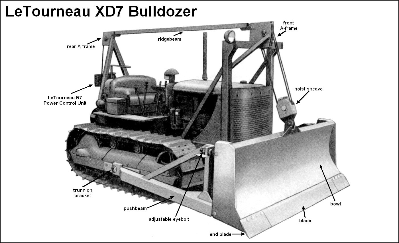 |
| LeTourneau XD7 Bulldozer Notice the adjustable eyebolts at the upper corners of the bowl. By tightening or loosening the screws, the bowl can be slightly tilted forward or backward to change the digging angle of the blade when needed. |
 |
| Seabee Caterpillar D7 with LeTourneau R7 PCU and LeTourneau XD7 Bulldozer, leveling an airfield. Notice the adjustable eyebolts at the upper corners of the bowl. Iwo Jima, Japan - June, 1945 |
 |
| Caterpillar D7 with LeTourneau R7 PCU and LeTourneau XD7 Bulldozer. |
- LaPlant-Choate R76F and R76R Trailbuilder: the R76F (front) and R76R (rear) trailbuilders consists mainly of the steel blade across the front of the tractor; the pushpoles and the main frame, which support the blade in front of the tractor; the tractor mountings , on which the rear ends of the main frame pivot; the front overhead group, the overhead beam and the rear overhead-brace assembly which support the sheaves over which the cable from the PCU travels to raise and lower the blade. The R76F or R76R trailbuilder was a cable-operated angledozer that can be operated by any type of front or rear-mounted PCU. The standard combinations for Caterpillar D7 tractors in service with the U.S. Armed Forces normally were: LaPlant-Choate R76F Trailbuilder with LeTourneau FTD7 front-mounted PCU and R76R Trailbuilder with LeTourneau R7 rear-mounted PCU. The blade of the Trailbuilder may be angled 30° right or left or used as a straight bulldozer. The blade may also be tilted up or down at either end by removing the front pushpole pins and changing the position of the pushpole in the jaws blade locks.

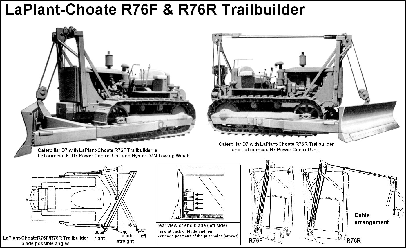 |
| LaPlant-Choate R76F and R76R Trailbuilder Notice the possibilitie of horizontal angulation of the dozer (left below) and vertical tilt (center below) |
 |
| Caterpillar brochure photo showing a D7 tractor equipped with LaPlant-Choate R76F Trailbuilder dozer controlled by a LeTourneau FTD7 PCU and a Hyster D7N Trailer Winch in the rear. |
 |
| A Caterpillar D7 with LeTourneau R7 PCU and LaPlant-Choate R76R Trailbuilder dozer working at the beach. South Pacific, 1944 |
 |
| A Caterpillar D7 with LeTourneau R7 PCU and LaPlant-Choate R76R Trailbuilder dozer from US Army gives an LCM(3) a helping push... Operation Plunder - Crossing of the lower Rhine Germany - March, 1945. |
- LaPlant-Choate R71 Trailbuilder (hydraulic): the R71 trailbuilder was a hydraulic-operated angledozer, designed for the same operations as the cable-operated R76F and R76R trailbuilders. The R71 trailbuilder consists mainly of the steel blade across the front of the tractor; the main frame and pushpoles with runner shoes which support the blade in front of the tractor; the tractor mountings, on which the rear ends of the main frame pivot; the hydraulic system which includes a hydraulic pump, control valve, piping, oil reservoir and two hydraulic jacks. The hydraulic pump is bracked-mounted to the fan-belt pulley of the tractor engine and provides the hydraulic power to operate the jacks of the trailbuilder to raise and lower the blade. The trailbuilder is attached to the outside of the track frames on pivot-type mountings, and is lifted and lowered by means of two jacks. The jacks are double-acting, which allows down-pressure to be applied to the blade, as well as lifting-power. The blade may be used in the straight or bulldozing position, or angled 30° or right or left-hand delivery. The blade may also be tilted the same way as with the R76F and R76R trailbuilders.

 |
| Caterpillar D7 equipped with LaPlant-Choate R71 Trailbuilder (hydraulic) with blade angled 30° to the right. |
| Caterpillar D7 tractor LaPlant-Choate R71 trailbuilder dozer clearing debris from street at Nantes, France - 1944 |
| Caterpillar D7 LaPlant-Choate R71 Trailbuilder (hydraulic) and the LeTourneau R7 PCU in the rear. The bulldozer is clearing rocks from roadway between Colli and Cema Italy - 1944. |
 |
| "We can do it" A british girl operating a civil Caterpillar D7 LaPlant-Choate R71 Trailbuilder (hydraulic). Somewhere in the countryside of England, 1943. |
- Bulldozers: (fixed blade) are used for moving rock , uprooting trees and stumps, leveling land, grading and maintaining roadways, digging holes and filling, stripping. A bulldozer blade was initially operated (or pushed) by a team of mules or horses. Early bulldozer blades, mounted on tracklaying tractors, were controlled by the operator by means of hand wheels. In the mid- to late 1920s, a hydraulic-controlled bulldozer blade was invented by LaPlant-Choate, and R. G. LeTourneau introduced a cable-controlled bulldozer, operated through a front- or rear mounted power control unit. With the time, the name bulldozer became associated with the complete bulldozer-equipped tractor, and not any longer with the attachment alone.
- Angledozers: (blades capable of being angled and tilted) are used for clearing, stripping, leveling, side-hill sloping, ditching, carving out roadways, building levees , and for airfield construction.
- Power control unit (PCU): used to operate other mounted equipment like bulldozers or angledozers and towed equipment like scrapers, graders or rooters.
- Pipelayers: are side-mounted cranes powered by the tractor, and will lift, lower, carry or bend pipes in pipeline construction. They are also useful in handling and placing poles and piles, setting machinery and in heavy loadlifting.
- Anglefillers: used for trench filling in combination with pipelayers, and eliminate the use of a separate backfiller or bulldozer.
- Winches: designed for towing purposes and for moving heavy loads that are too heavy to be properly handled with the tractor 's drawbar. They are also very useful in recovering disabled or stuck vehicles
| Caterpillar D7 bulldozer LeTourneau R7 power control unit | |
|---|---|
| Type | Crawler heavy tractor M1 |
| Place of origin | United States |
| Service history | |
| In service | 1911-1945 |
| Used by | Allies |
| Wars | WWII, Korea, Vietnan |
| Production history | |
| Designer | Caterpillar Inc. |
| Designed | 1938 |
| Manufacturer | Caterpillar Inc.- American Car & Foundry |
| Produced | 1938 - |
| Number built | + 39.000 |
| Variants | see text |
| Specifications | |
| Weight | 14.400 Kg |
| Length Widht Height | 4.114 mm 2.539 mm 2.40m |
| Crew | 1 |
| Engine Transmission | Cat D8800 Diesel, 60/90 HP 4 cyl. 13.617 cc. 5 gears fwd. x 4 rev. |
| Speed forw. | 18 Km/h |
| Speed rev. | 11,2 Km/h |
| Fuel tank | 247 liters |
| Fuel consum. Traction cap. Eletrical sys. | 22 liters/ hour 11.500 kg. 6 Volts |
 |
 |
| When life offers to you a lemon, make lemonade!!! |
 |
| The bald one is a very brave man!!! |
 |
| The engine is more complex than many complete kits... zillions of details and little pieces... But let's be strong!!! |
 |
| And while we're talking about details, why not go into more detail where it's needed: fuel injection ducts, made with thin copper wire |
 |
| Much better... |
 |
| fuel injection ducts, going from the injection pump to the individual injectors in the cylinder heads... |
 |
| Of course, all these countless little pieces drive anyone crazy!!! |
 |
| As Captain Edmund Blackadder would say: Wibble!! |
 |
| It's crazy, but the engine is a beauty... |
 |
| Installing the engine on the tractor chassis right view |
 |
| The engine on the tractor chassis left view |
 |
| Completing the construction of the tractor cockpit... right view |
 |
| Notice the tractor's semi-elliptical equalizer spring... |
 |
| The two track-roller frame assemblies, after its construction, waiting next to the tractor chassis |
 |
| The two track-roller frame assemblies, glued in position... Left view |
 |
| The alignment of the track-roller frames are fundamental for the final finishing of the kit. Right view |
 |
| Rear view. Notice the rear end of the tractor's drawbar, supported by a plate which allows the drawbar to swing freely, or to be pinned in any of five positions. |
 |
| Seabee badge |
 |
| Seabee 34th Naval Construction Battalion shield |
 |
| The real 34th CB badge (left) and the redrawn drawing, right. |
| Seabee 34th Naval Construction Battalion badge |

 |
| Preparing for the "internal" painting... Notice new details in copper-wire in the engine Right side |
 |
| Notice new details in copper-wire in the engine Left side |
 |
| Olive drab in the engine and internal parts of engine hood |
 |
| Adding color details to engine and a little washing... Diesel engines are very "oily"... Right side view |
 |
| Color details in the engine with washing... Diesel engines are very "oily"... Left side view |
 |
| Top engine cover glued in place. Many details are lost, but still, it's a beautiful sight... Left view |
 |
| Top engine cover glued in place. Notice the air filter in place. Right view |
 |
| Mea culpa...mea culpa!!! |
 |
| Built the drums of the LeTourneau R7 PCU is annoying... Self-harm is more fun... |
 |
| These drums are just complicated to build... |
 |
| The PCU secondary pulleys are a true HORROR!!! |
 |
| This is the WORST PART of the kit!! |
 |
| I swear I prefer... |
 |
| The "Treasure Map" for you to transform the tractor from the civil version into a military one. |
 |
| Notice the steps and headlights in the tractor's rear. Military version, by the Military booklet!! |
 |
| Missing tree and parts... Man, let's do this in scratch... We can do!! |
 |
| First, let's draw the outline and cut two identical pieces out of plasticard, with a scalpel and patience... |
 |
| Once the pieces are done, let's unite with the rest of the kit... |
 |
| After 15 minutes of work, the missing front A-frame's pulley set is ready... |
 |
| The front A-frame's pulley set in position left view |
 |
| The front A-frame's pulley set in position...And that's a relief... right view |
 |
| Immortal Gods!! Am I doing something wrong??? |
 |
| Notice the rear A-frame offset to the right |
 |
| The rear pulley done... Notice the the endings of the ridgebeam It's a relief to finish those details that were missing... |
 |
| Final details: bolts (red arrows) and testing the cover of ridgebeam (blue) left side |
 |
| Final details: bolts (red arrows) and testing the cover of ridgebeam (blue) right side |
 |
| Tibetan monk patience, now... Main parts cut and separated. The Dc3 and Dc2 parts cannot be lost or broken... They are EXACTLY in number...as well as the pads of the links... The Dc1 pins come with a lot of extras... don't worry... |
 |
| Build 70 sets with Dc3 and Dc1 pieces... Leave 2 Dc3 pieces without pins (Dc1) Notice the burrs in the little parts... |
 |
| The 70 sets after cleaning: no more burrs!! |
 |
| The Map of Treasure... Notice the the places to glue and not glue, so that the track can be malleable... |
 |
| The start of a track... Work with method and patience... it seems to be horrible, but it's just boring!!! |
 |
| First track under construction... |
 |
The two tracks done... Notice the absence of the pads... They will be installed last... |
 |
| "Closing" the track with Plastruct rod... Easy!! |
 |
| Notice the the direction of the track links, at its top. The future position of the pads depends on the position of the links... Right track: The aperture of the "V" points forward, in the top portion of the track. |
 |
| Left track: the same care when installing the links: The aperture of the "V" points forward, in the top portion of the track. |
 |
| Notice the links, clean and burr free... right view |
 |
| Track links, clean and burr free... leftt view |
 |
| The ventral view of pad, where the holes and pins should line up for the glue. This is why the orientation of the "V" opening was important... |
 |
| Gluing the pads to the links, with the teeth of the pads pointing forward... |
 |
| A good tip is to enlarge the holes of the pads with a 1mm diameter dental drill, manually rotated, to allow a better adjustment of the position of each pad... |
 |
| Something like that... note that the hole shouldn't go through the thickness of the pad. That's why I used the drill by hand... |
 |
| Left track ready!!! |
 |
| ..and the right, also!!! |
 |
| The idea: notice the exhaust... right view |
 |
| The evidences of the real detail... Please, quiet!!! |
 |
| Left side: a little big detail... Notice the headlights in the front A-frame, too... |
 |
| Dozer time, now!!! Gluing the parts... |
 |
| The dozer in position... Notice the radiator armour in place... |
 |
| The LeTourneau WCK7 angledozer is really beautiful very well done, MiniArt!!! Left view |
 |
| Notice the hoist sheave installed above the dozer... |
 |
| The LeTourneau WCK7 angledozer in position right view |
 |
| Rear view The dozer is in dry-fit... |
 |
| Man... lever in position, with a plastic block to support in the correct position while the glue dries... |
 |
| Notice the "isolation" of the motor area and the wire rope of the PCU. right view |
 |
| "Isolation" of the motor area left view |
 |
The white primer applied to kits and accessories. I am painting and applying decals together with the |
 |
| The two Seabee girls with colors!!! US Navy bluish gray |
 |
| My cake recipe...Attention: I'm not a poster-boy for Vallejo!! I like and use this awesome paint... as well as many others... At this point (and many others...) I'm not a radical or Shiite rivet counter! |
 |
| Fifty shades of Navy grey... Exciting isn't it??!! |
 |
| The angledozer with shades... |
 |
| and the two Seabee girls with a good layer of Pledge to avoid the infamous silvering... |
 |
| Caterpillar D7 Seabee markings |
 |
| Print screen of my computer... You can see the markings and the Seabee badge in detail, in the left of the screen. I copy this art with Control+c and paste the image in the CorelDRAW software (see below) |
 |
| The Seabee badge is paste in the CorelDRAW. |
 |
| Getting the size of the space where the badge will be installed... |
I'm not going to explain all the steps here, because they are long and complicated, but there are "n" tutorials on the Internet about it... The important thing is to know how many millimeters your full-size image of the kit will have to fit in the desired space. In this case, the size of the Seabee badge was 8mm in diameter. Repeat this measurement on all the drawings on your decal sheet...
 |
| All drawings in their actual sizes, vectorized and grouped for future printing. |
Step 04 - Printing your decals on plain paper (field test): After all the drawings are ready in the CorelDRAW software and in their respective sizes, print your "decal sheet" on an A4 sheet to do a "field test", that is, to test if the sizes you obtained with your ruler were correct.
 |
| The "decal sheet" printed in paper A4. Notice the size of the drawings... |
Now, cut the paper with fine scissors as close as possible to the drawing and, with a drop of water, apply the "decal" in the desired place to test the size... A picture is worth a thousand words!!!
 |
| The "paper-decal-sheet" in front of the kit... The sizes seem correct to me...Let's see individually... |
 |
| The engine hood area: the Seabee badge is perfect, the number 59 needs to be reduced a little the census number is correct and the Allied Star in the top of the hood can be increased a little... |
 |
| Yes..no doubt: the Allied Star can be increased a little... |
 |
| Rear markings: the Star and number 59 are perfect; the markings in the Power Control Unit It needs to be reduced a little... |
 |
| Front view; the letters are ok and the Allied Star also... In this case, I'll use a stencil, for painting the star, not a decal... The holes would turn the decal installation into hell!!! |
 |
| Print screen of my computer: above, the Caterpillar D7 decals; below, the Chevrolet G7107 ones. |
 |
| The artwork printed in a A4 paper sheet. Notice the size of the area that will be covered by the clear decal sheet. |
 |
| The transparent decal sheet over the primary impression, stabilized by the two strips of adhesive tapes. Everything clean and organized... |
 |
| The decal sheet printed in my Laserprint... |
 |
| Notice the adhesive tapes in position, away from the drawings... |
 |
| Removing the decal sheet from the A4 host sheet |
 |
| The decal sub-sheets, in front of each girl... Now, just apply!! |
 |
| References.... |
 |
| Adapting Verlinden's metal stencil on the Cat D7's nose... Verlinden rules!!! |
 |
| A very, very good stuff US stars template no. 1 - Verlinden |
 |
| Painting in black, with Andrea Colors... Indeed, Kojak love many brands of paints... |
 |
| And the result: good job, Sailor!!! |
 |
| Now, Panzerserra decals... |
 |
| Painting and decals togheter!!!! |
 |
| Installing the angledozer in position.... Indeed, a good job!! |
 |
| Right side!! |
 |
| Front view |
 |
| rear view |
 |
| Left view |
 |
| The front steel cables... left view |
 |
| The front steel cables... right view |
 |
| The steel cable from Power Control Unit. I choose run my wire rope directly from the PCU drum to the tractor's A-frame rear pulley, as in many original photos. I didn't run the cable through the PCU's "butterfly" pulleys for sanity's sake... |
 |
| Caterpilar D7 with LeTourneau R7 Power Control Unit and LeTourneau WCK7 angledozer - Seabees (US Navy) 34th Naval Construction Battalion Florida Island (Solomons Islands) - September, 1943. |
 |
| Caterpilar D7 with LeTourneau R7 Power Control Unit and LeTourneau WCK7 angledozer - Seabees (US Navy) left view |
 |
| Caterpilar D7 with LeTourneau R7 Power Control Unit and LeTourneau WCK7 angledozer - Seabees (US Navy) 3/4 left rear view |
 |
| Caterpilar D7 with LeTourneau R7 Power Control Unit and LeTourneau WCK7 angledozer - Seabees (US Navy) left rear view |
 |
| Caterpilar D7 with LeTourneau R7 Power Control Unit and LeTourneau WCK7 angledozer - Seabees (US Navy) left rear view |
 |
| Caterpilar D7 with LeTourneau R7 Power Control Unit and LeTourneau WCK7 angledozer - Seabees (US Navy) right view |
 |
| Caterpilar D7 with LeTourneau R7 Power Control Unit and LeTourneau WCK7 angledozer - Seabees (US Navy) |
 |
| Caterpilar D7 with LeTourneau R7 Power Control Unit and LeTourneau WCK7 angledozer - Seabees (US Navy) 3/4 right front view |
 |
| Caterpilar D7 with LeTourneau R7 Power Control Unit and LeTourneau WCK7 angledozer - Seabees (US Navy) 3/4 left front view |
 |
| Caterpilar D7 with LeTourneau R7 Power Control Unit and LeTourneau WCK7 angledozer with Kojak and Rover, the dog. |
 |
Caterpilar D7 with LeTourneau R7 Power Control Unit and LeTourneau WCK7 angledozer two heavy-duty girls!! |
 |
Caterpilar D7 with LeTourneau R7 Power Control Unit and LeTourneau WCK7 angledozer |
 |
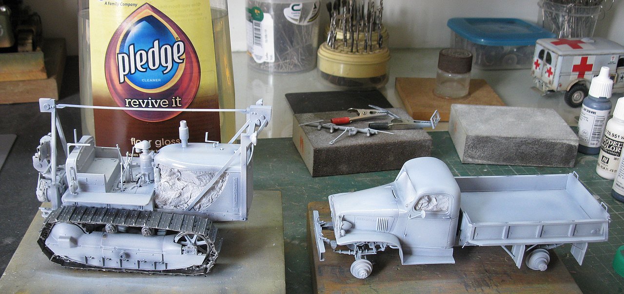
| Two Seabee girls, side by side: Caterpilar D7 with LeTourneau R7 Power Control Unit and LeTourneau WCK7 angledozer and Chevrolet G7107 4X4 1,5t cargo truck (G506) |
 |
| Caterpilar D7 with LeTourneau R7 Power Control Unit and LeTourneau WCK7 angledozer - Seabees (US Navy) 34th Naval Construction Battalion Florida Island (Solomons Islands) - September, 1943. |
 |
| (dedication painting to the Seabees, at the Seabee Naval Museum) |