
Sappers!!!
The subject of our project is a vehicle specially designed to facilitate the access for allied armoured forces during D-Day landings. Today we'll talk about one of Hobbart's useful and weirdest Funnies: the Churchill Mk.III AVRE S.B.G. (Small Box Girder) assault bridge.

History:
The Churchill Infantry Tank was a great line of heavy tanks that sported the name of the famous Prime Minister, Sir Winston Churchill:
 |
Winston Churchill handling a .45 Thompson submachine gun, during the visit to the coastal defense positions near Hartlepool County Durham, England - 31 July, 1940 |
The legend says that when presented to the prototype tank (then unnamed) Sir Winston Churchill reportedly said: "He's a tough guy, just like me ..."
 |
| Churchill inspecting a Churchill Mk I |
But leaving the story (and the legends) aside, the main feature of this model of tank is the a high-speed gun in the turret and a howitzer in the front hull, following the "armour fashion" of the tanks at the time ...
 |
| Churchill Mk I with howitzer in the front hull |
...such as the French Char B-1 bis heavy tank:
 |
| Char B1 bis 452 named “VERDUN II” of 1st Division Cuirassée de Réserve. |
... and the american M3 medium tank Lee:
 |
| Women war workers test driving a brand new M3 Lee medium tank. |
But in the particular case of Churchill, this arrangement of armament generated a deficiency that would only be detected later on the battlefield: the howitzer had a small elevation capacity. Due to the initial low velocity of the projectile (180m/s), this weapon would need to have a high degree of elevation to allow for a parabolic shooting trajectory. But as the howitzer was installed in the front portion of the tank and as Churchill had a much lower hull than his contemporaries,, the weapon was not effective enough, generating a tactical disadvantage in the use of that vehicle (effective firing range: only 1,800 m).
 |
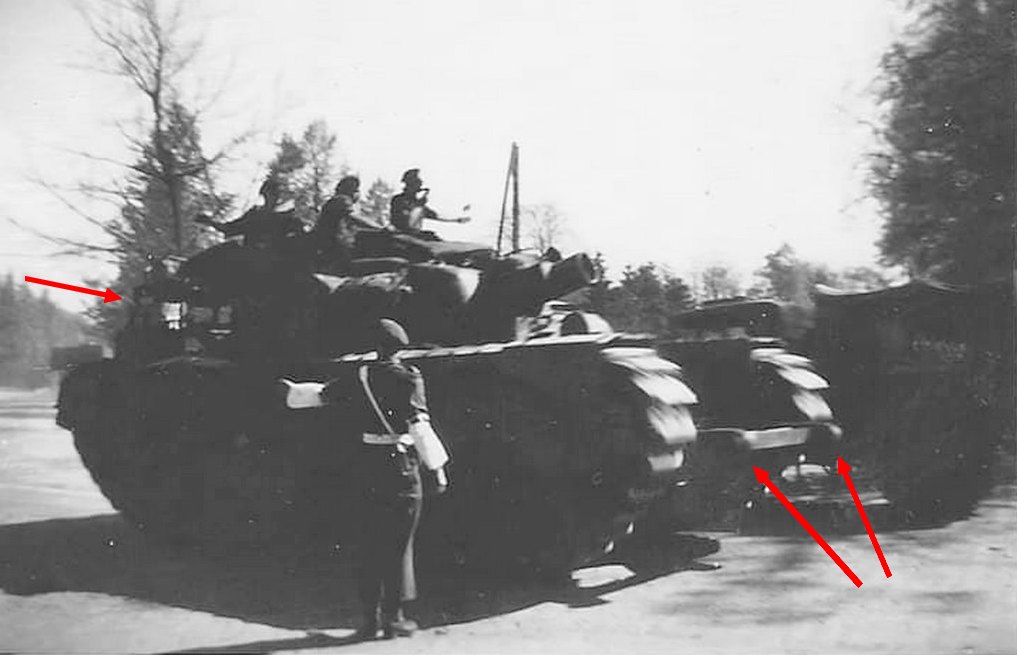
| Churchill Mk I - Notice the exposed tracks and the air filters in the side of the hull. |
The Tank, Infantry, Mk IV (A22) was a heavy British infantry tank used in the Second World War, best known for its heavy armour, large longitudinal chassis with all-around tracks with multiple bogies, and its use as the basis of many specialist vehicles. It was one of the heaviest Allied tanks of the war. The origins of the design lay in the expectation that war in Europe might be fought under similar conditions to that of the First World War and emphasised ability to cross difficult ground. The Churchill was rushed into production in order to build up British defences against an possible German invasion and the first vehicles built had flaws that had to be overcome before the Churchill was accepted for wide use. After several Marks had been built a better armoured version - the Mark VII - entered service.
The Churchill was used by British and Commonwealth in North Africa, Italy and North-West Europe. In addition many were supplied to the USSR and used on the Eastern Front.
The predecessor: A20
Initially specified before the outbreak of the Second World War the (General Staff designation) A20 was to be the replacement for the Matilda II and Valentine infantry tanks.
In accordance with British infantry tank doctrine and based on the expected needs of World War I-style trench warfare, the tank was required to be capable of navigating shell-cratered ground, demolishing infantry obstacles such as barbed wire, and attacking fixed enemy defences; for these purposes, great speed and heavy armament was not required.
 |
British Infantry Tank - Matilda Mk II A12 - Canadian training - 1941. |
 |
| Valentine Mark VI tank at Base Borden Military Museum |
The vehicle was specified initially to be armed with two QF 2 pounder guns each located in a side sponson, with a coaxial BESA machine gun. A third BESA and a smoke projector would be fitted in the front hull.
The specification was revised to prefer a turret with 60 mm of armour to protect against ordinary shells from the German 37 mm gun. Outline drawings were produced based on using the A12 Matilda turret and the engine of the Covenanter tank. Detail design and construction of the A20 was given to the Belfast shipbuilders Harland and Wolff who completed four prototypes by June 1940. During the construction period the armament was reconsidered which including fitting either a 6 pounder or a French 75 mm gun in the forward hull. In the end a 3-inch howitzer was chosen.
 |
| A20 prototype (draw) - Notice the hull armament |
The A20 designs were short-lived however, as at roughly the same time the emergency evacuation of the British Expeditionary Force from Dunkirk occurred.
 |
| A20 prototype with Matilda type turret |
At 43 tons, with a 300 hp flat-12 Meadows engine, the A20 had limited power compared to the 18 ton Covenanter.
This was a less serious limitation than it might appear, owing to the British distinction between the high-speed cruiser tanks and the slow-speed infantry tanks. Vauxhall were approached to see if they could build the A20 and one example was sent to Vauxhall at Luton to see if they could provide an alternative engine. To this end they developed a flat-12 petrol engine. For speed of production, this engine was based on a Bedford six-cylinder lorry engine, giving rise to its name of "Twin-Six". Although still a sidevalve engine, the engine was developed with high squish pistons, dual ignition and sodium-cooled exhaust valves in Stellite seats to give 350 bhp.
 |
| Covenanter tank |
The A22 tank:
With France conquered, the scenario of trench warfare in Northern Europe was no longer applicable and the design was revised by Dr. H.E. Merritt, Director of Tank Design at Woolwich Arsenal, based on the combat witnessed in Poland and France. These new specifications, for the A22 or Infantry Tank Mark IV, were given to Vauxhall in June 1940.
With German invasion looking imminent and the United Kingdom having lost most of its military vehicles in the evacuation from France, the War Office specified that the A22 had to enter production within the year. By July 1940 the design was complete and by December of that year the first prototypes were completed; in June 1941, almost exactly a year as specified, the first Churchill tanks began rolling off the production line.
 |
| A22 prototype |
This hasty development had not come without cost though, as there had been little in the way of testing and the Churchill was plagued with mechanical faults. Most apparent was that the Churchill's engine was underpowered and unreliable, and difficult to access for servicing. Another serious shortcoming was the tank's weak armament, the 2 pounder (40 mm) gun, which was improved by the addition of a 3 inch (76,2mm) howitzer in the hull to deliver an HE shell albeit not on a howitzer's usual high trajectory.
These flaws contributed to the tank's poor performance in its first use in combat, the disastrous Dieppe Raid in August, 1942.
 |
| Churchill Mk I (early) |
Production of a turret to carry the QF 6 pounder gun began in 1941 but problems with the plate used in an all-welded design led to an alternative cast turret also being produced. These formed the distinction between Mark III and Mark IV.
The poor performance of the Churchill nearly caused production to be ceased in favour of the upcoming Cromwell tank; it was saved by the successful use of the Mk III at the Second Battle of El Alamein in October 1942.
 |
| Churchill Mk III (early) |
The second major improvement in the Churchill's design, the Mk VII saw first used in the Battle of Normandy in 1944. The Mk VII improved on the already heavy armour of the Churchill with a wider chassis and the 75 mm gun which had been introduced on the Mk VI.
 |
| Churchill Mk VII in trials |
It was primarily this variant, the A22F, which served through the remainder of war and was re-designated as A42 in 1945. The Churchill was notable for its versatility and was utilized in numerous specialist roles, with the AVRE versions being the most interesting and numerous.
Churchill AVRE (Assault Vehicle, Royal Engineers) version:
The Churchill AVRE (Assault Vehicle, Royal Engineers) was developed after the Dieppe raid in an attempt to make combat engineers less vulnerable while they were attempting to destroy enemy defences.
 |
| Churchill Mk IV AVRE |
The AVRE was developed from a suggestion made by a young (29 years old) Lieutenant John James Denovan, of the Royal Canadian Engineers, but attached to the Special Devices Branch of the Department of Tank Design.
 |
| Lieutenant John James Denovan. |
His idea was for a tank with as much of the standard internal equipment as possible removed and replaced with storage space for the sapper's equipment, tools and explosives. The Churchill was chosen because of its combination of a large interior, thick armour and side access door, and a prototype was developed for the Department of Tank Design by the 1st Canadian M E Company.
The crew of six were drawn from the Royal Engineers, except for the driver who came from the Royal Armoured Corps. One of the RE crew was a demolitions NCO sapper responsible for priming the "Flying dustbin" as well as leading or supervising when they dismounted from the tank (easily done through the side hatches) to place demolition charges ("Wade" charges).
 |
| "Flying dustbin" petard |
The AVRE had the main gun replaced by a Petard Mortar. This fired a forty pound (18 kg) HE-filled projectile (nicknamed the Flying Dustbin) 150 yards (137 m). The "Dustbin" could destroy concrete obstacles such as roadblocks and bunkers. This weapon was unusual in that it had to be reloaded externally - by opening a hatch and sliding a round into the mortar tube from the hull.
 |
| Petard mortar in the Churchill Mk IV turret |
 |
| The mortar and the petard |
The 290mm muzzle loading mortar was developed separately, by Colonel Blacker, the designer of the Blacker Bombard, a spigot mortar built for the Home Guard.
 |
| Home Guard soldiers operate a 'Blacker Bombard' spigot mortar during training at No. 3 GHQ Home Guard School Onibury near Craven Arms - Shropshire, 20 May 1943. |
He was asked to design a version of the mortar that could be mounted on a tank, and produced a mortar that could fire a 18 Kg (40 lb) high explosive shell known as the Flying Dustbin. See below a film with AVRES in training action. You can see a Churchill AVRE S.B.G in the first seconds, an AVRE fascine and a Churchill Mk.III AVRE firing his huge mortar against a bunker...
A massive spring soaked up the 20 tons of recoil and used the energy to recock the mortar. At the Hankley Common demonstration this mortar was mounted to a Churchill tanks. After using shells fused for air burst to clear a 8,5 meters wide gap through a minefield, the mortar then fired twelve shells directly at a 1,8 meters thick concrete wall, creating a gap wide enough for a tank.
The two designed were merged to create the AVRE. Around 700 were produced by converting Churchill Mk IIIs and IVs, of which 180 had been completed by the D-Day landing, where they were used by the 1st Assault Brigade of the 79th Armoured Division.
 |
| 79th Armoured Division badge |
The AVRE was given standard attachment points that could be used to carry a wide range of specialised equipment, including fascine carriers that could drop their brushwood bundles into ditches or at the base of barriers, a variety of mine sweeping devices, a Small Box Girder bridge, 'bobbin' carpet laying tanks and the 'Goat' explosive device. Here are some specialized versions (among others...) of AVRE:
- Bridgelayer - The Bridgelayer conversion was based on a Churchill MK-III or MK-IV. The bridge could carry a 18 meters tank or Class 40 wheeled vehicles, and the driver operated the laying mechanism; the only other crew member was the commander.

- Bobbin - A reel of 3.0 meters wide canvas cloth reinforced with steel poles carried in front of the tank and unrolled onto the ground to form a "path", so that following vehicles (and the deploying vehicle itself) would not sink into the soft ground of the beaches during the amphibious landing.

- Fascine - A bundle of wooden poles or rough brushwood lashed together with wires carried in front of the tank that could be released to fill a ditch or form a step. Metal pipes in the center of the fascine allowed water to flow through.
 |
| Two Churchills AVRE Fascine leading Churchills ARKs |
- Small Box Girder was an assault bridge that was carried in front of the tank and could be dropped to span a 9.1 meters gap in 30 seconds.
 |
| Churchill Mk.IV AVRE Small Box Girder |
- Bullshorn Plough. A mine plough intended to excavate the ground in front of the tank, to expose and make harmless any land mines.

- Double Onion. two large demolition charges on a metal frame that could be placed against a concrete wall and then detonated from a safe distance. It was the successor to the single charge device Carrot.

- CIRD. The Canadian Indestructible Roller Device (CIRD) consisted of two arms attached to the side of the tank, each supporting a heavy roller. The roller was suspended in such a way it could jump in the air and rotate in an arc round the arm when a mine was detonated, thus reducing the chance of the rollers being blown off.

The AVREs played an important part in the success of the British and Canadian landings on D-Day, where their spigot mortar was especially valuable, destroying a number of German strong points, the most famous being the Sanatorium at Le Hamel. They continued to operate successfully during the liberation of Europe by the Allies, until the end of WWII., and later versions of the AVRE tank remained in use long after the Churchill had been retired.
Churchill AVRE - S.B.G. (Small Box Girder) assault bridge:
The Churchill AVRE S.B.G.assault bridge was evolved by the Canadian Army in April 1943, as a method for wall or ditch crossing in assault. It consisted of a small box girder bridge fitted to the front of the Churchill AVRE and adapted for quick release.
 |
Churchill Mk.IV AVRE - S.B.G. (Small Box Girder) assault bridge in trials, for D-day landings. Notice the absence of petard mortar in the Churchill Mk IV turret |
 |
Churchill Mk.IV AVRE - S.B.G. (Small Box Girder) assault bridge in trials, for D-Day landings. Notice the overload imposed on the front portion of the tank suspension by the weight of the bridge. |
 |
| Commandos of No. 4 Commando, 1st Special Service Brigade move inland from Queen Red beach, Sword Beach area Churchill AVRE S.B.G. assault bridge can be seen in the background Normandy, France - 6 June 1944. |
The bridge weighed four tons, was 10,36 meters long, was able to take a load of 40 tons, and was controlled by a winch mounted on the upper rear deck of the Churchill AVRE and could be deployed from inside the tank. The process took approximately 30 seconds. A considerable improvement in relation to the installation of the SBG bridge by sections, by the engineering groups.
 |
| A S.B.G assault bridge being placed over an obstacle by a Churchill AVRE, at a training ground. This process was very quick to perform and could be completed from inside the tank. England - 1943. |
 |
| Drawings of period technical manuals describing the installation of a S.B.G. assault bridge by the "old school" way. The detail of the "sapper" balancing on the second drawing is priceless! Imagine it under enemy fire... Poor sappers... |
The bridge consisted of 4 sections connected together by cross beams to form a two-track crossing. A cable and a winch were attached to the engine deck, and an A-shaped frame was attached to the front of the Churchill AVRE tank. The bridge was suspended from the front of the tank at an angle of about 60 degrees. A problem in this tank + bridge composition was the weight of the bridge hanging from the Churchill's bow, that compressed the front suspension bogies and lifted the rear bogies from the ground. Thus, steering the tank when cornering was not easy.

The bridge could surmount a 4,5 meters wall or span a 9,14 meters gap. The design had been formally adapted by the British Army in the 1930s and copied by many countries prior to the war (including Germany).
 |
| Bren carrier crossing the a Small Box Girder bridgebuilt by Northern Ireland Royal Engineers over the River Ballinderry, near Ardtrea, Co. Tyrone - December, 1942. R.E. Units, 61st Div. At that time, S.B.Gs were transported by heavy trucks and their installation was slow and laborious (see drawing above...) |
 |
| British 2nd Army: Second wave troops of 9th Canadian Infantry Brigade, probably Highland Light Infantry of Canada, disembarking with bicycles from LCI(L)s (Landing Craft Infantry Large) onto 'Nan White' Beach, Juno Beach Area at Bernières-sur-Mer, shortly before midday on 6 June 1944. Notice the "white" S.B.G. assault bridge, poured over the beach wall, allowing the entry of allied armored vehicles. (in the middle of the image, right behind the bulldozer) |
 |
| Close up of the same S.B.G. assault bridge of picture above, few hours later. The bridge was left by a Churchill AVRE, immediately after landing. Notice the white color of the bridge. 'Nan White' Beach, Juno Beach Area at Bernières-sur-Mer Courseulles-sur-mer area - Normandy - France , 6 june 1944. |
After the Churchill AVRE S.B.G. ejected the bridge, they could continue in the Theater of Operations as a normal tank, helping the infantry advance with their powerful mortar.
 |
| Universal Carriers of 2nd Middlesex Regiment (3rd Division's MG battalion) passing by a Churchill Mk.IV AVRE S.B.G. from 79th Armoured Division - 5th Assault Regiment - 77th Assault Squadron La Brèche d'Hermanville - Normandy, France - 6 June, 1944. Notice in the front armor of the tank the device that carried the bridge. She must have used the bridge early on in the landing operations. |
 |
| Close up of the picture above... Notice the winch mounted on the upper rear deck (green) and the front bracket for the bridge (red). Churchill Mk.IV AVRE S.B.G. "BULLDOG - 2B" - assault bridge from 79th Armoured Division - 5th Assault Regiment - 77th Assault Squadron. |
 |
| Troops of 3rd Division on Queen beach, Sword area, 6 June 1944. On the left, medics attend to wounded next to a disabled Churchill Mk.IV AVRE S.B.G. from 5th Assault Regiment, Royal Engineers. The AVRE has already laid its bridge. Notice the rear details of the tank... |
 |
| Churchill AVRE SBG assault bridge - rear view After ejecting the bridge, this AVRE SBG continues ready to fight. Watch the winch on the aft deck. Netherlands - late 1944 |
 |
| A Churchill Mk.IV AVRE SBG without herassaultbridge. Even though the photo is terrible, it is possible to identify the bridge coupling device in the bow and the winch in the aft. |
 |
| A Small Box Girder bridge after successfully placed in an obstacle on the landing beach. Again, notice the white color of the bridge. |
Below, two snapshots from a newsreel about landings on the Sword Beach (Queen Red area), in 6 June, 1944. Notice the Churchill AVRE S.B.G with his "white" bridge erected, immediately after landing, near a boathouse, on the beachfront, in the first snapshot and with the bridge lowered, to be installed, in the second image
 |
| Churchill AVRE S.B.G with his "white" bridge erected |
 |
| ...and with bridge lowered, to be put in its place. Sword Beach - Normandy, 6 June 1944. |
Churchills AVRE Fascines were often used in conjunction with Churchills S.B.G. assault bridge, working like a team. The Churchill AVTR S.B.G. assault bridge was not very popular with captains and helmsman of landing ships, as the bridges "caught" the wind. Their presence in the front of the landing ships made it difficult to control the vessel, so the bridges were often loaded as back far as possible on the deck.
 |
| 79th Armoured Division training for the Invasion of Europe: Sherman tanks, Churchill AVRE Fascine, Sherman Crab and Churchill AVRE S.B.G. assault bridge loaded into a landing craft - Saxmundham-Ipswich area, 28 January 1944. |
The next 3 photos were kindly sent by our colleague Duncan Gunn (group admin of Halftrack Engineer ARV Truck - Facebook) showing footage from D-Day, with Churchills AVRE S.B.G.s going into battle... Thank you so much, Duncan!!!
 |
| Churchill AVRE SBG assault bridge, maneuvering in reverse, just loading onto a LCT - notice the white (-ish) color of the bridge and the future position of SBG, further aft in the boat... via Duncan Gunn - Facebook |
 |
| LCI in convoy with 2 X LCT loaded with Churchills AVRE SBG assault bridges. English Channel - 6 june, 1944 - D-Day. Notice the positions of SBGs further aft, in the boats... via Duncan Gunn - Facebook |
 |
| Photograms of a color film showing LCT loaded with Sherman Crab, Churchill AVRE fascine under camo netting and Churchill AVRE SBG assault bridge via Duncan Gunn - Facebook |
To enable the AFV to climb over high obstacles, the Churchill AVRE S.B.G. released its bridge at an angle against the obstacle and then withdrew...
 |
| 79th Armoured Division AVREs training to overcome obstacles... Vehicles are about to disembark of landing craft, with the Churchill Mk.III AVRE S.B.G. going to extend the bridge over the ravine, while the Churchill Mk.IV AVRE Fascine wait to climb the bridge and pour the fascine over the adjacent gap. Saxmundham-Ipswich area -January, 1944 |
Then, the Churchill AVRE fascine climbs over the bridge and at the top, ejects its fascine roller, so that it fills the height of the wall so that it and other vehicles can safely pass the obstacle. This operation can be repeated until the fascines "fill in" the posterior portion of the obstacle... Look at the photos in sequence below the training of this action: the Churchill fascine made a mistake by ejecting the fascine too far forward or did not wait for another "colleague" fill the void, because when descending, the hull of the tank did not rest on the fascine, generating the possibility of a jam:
 |
| The Churchill AVRE fascine climbing by the SBG assault bridge... So far, so good!!! |
 |
| Ops...the fascine after being ejected, it rolled much further... Notice that the wooden cradle also fell (next to the wall), which may have caused the failure... The Churchill's driver is a balanced lad, by Jove! The correct thing would be to back off and allow another Churchill AVRE fascine to complete the service... |
 |
| But our intrepid driver decided to take a chance and... ouch!! Snout buried in the mud!!!! |
 |
| Again, the Churchills AVRE Fascine and S.B.G. working togheter. Start of Operation Veritable - Germany, 8 February 1945 |
 |
| Churchill Mk.III AVRE S.B.G. with his co-worker Churchill AVRE Fascine. Somewhere in Europe, Autum, 1944. |
The Churchills AVRE S.B.G. assault bridges were used extensively during the Allied invasion of Normandy and in other battles on the European continent until the end of the war. Another theater of operations in which they were widely used was in the Liberation of the Netherlands, due to the geography of the region.
%20bridge%20warm%20themselves%20around%20a%20fire%20near%20Venlo,%2030%20November%201944.jpg) |
| The crew of a Churchill Mk.IV AVRE with SBG (Small Box Girder) bridge warm themselves around a fire, near Venlo - Netherlands -30 November 1944 |
 |
| Churchill Mk.III AVRE S.B.G. assault bridge waiting in the side of road. Battle of Overloon - Netherlands - October, 1944. |
 |
| Churchill AVRE S.B.G. assault bridge waiting for action, with a a group of happy Dutch people!! Netherlands - late 1944. |
 |
| Dieppe's hard and bloody lessons were finally learned: A Churchill Mk.IV AVRE S.B.G. assault bridge (notice the bridge rack, on the bow of the tank and the winch on the upper rear deck) climbing over the Atlantic Wall, after having deposited his precious white bridge in the correct place... This odd and funnie vehicle saved countless lives... |
Specs:

Churchill Mk III AVRE S.B.G. assault bridge | |
|---|---|
Type | Infantry - sapper tank |
Place of origin | United Kingdom |
Service history | |
In service | 1941–52 |
Used by |
|
Production history | |
Designer | |
Manufacturer | |
Produced | 1941 to 1945 |
Number built | 754 AVRES |
Variants | Mk.III & Mk.IV |
Specifications | |
Weight | 40.1 tons |
Length | 7.44 m |
Width | 3.25 m |
Height | 2.49 m |
Crew | 6 |
Armour |
|
Main armament | Spigot mortar 290mm firing a 18 kg "Flying Dustbin" petard (26 rounds) |
Sec. armament |
|
Engine | Bedford 12-cyl., 4 stroke, water-cooled, horizontally opposed, L-head petrol engine 350 hp @ 2,200 rpm |
Power/weight | 9.1 hp / tonne |
Transmission | Merritt-Brown 4-speed constant-mesh epicyclic gearbox |
Suspension | Coiled spring |
Op. range | 90 km |
Speed | 24 km/h |
Steering system | Triple differential steering in gearbox |
S.B.G. assault bridge | |
|---|---|
Type | small assault bridge |
Place of origin | United.Kingdom |
Service history | |
In service | 1932–52 |
Used by |
|
Specifications | |
Weight | 4 tons |
Length | 10.36 m |
Width | 3.30 m |
Height | 1.30 m |
Horizontal obstacle Vertical obstacle | 9.15 m 4.5 m |
The kits:
While AFV Club does not launch the desired and expected Churchill Mk.IV AVRE with SBG bridge (# AF35342) on the market, let's follow the old but effective recipe of an AFV Club Churchill Mk.III AVRE (#AF35167) with a Resicast resin conversion kit S.B.G. Assault Bridge (#35.1119).
 |
| After all, Kojak is not scared of anything!!! The bald one with Churchill Mk.III AVRE AFV Club kit (#AF35167) with Resicast resin conversion kit S.B.G. Assault Bridge (#35.1119). |
Starting by the book, as usual. This project will be executed in parallel with the assembly of a Churchill Mk.IV AVRE Fascine AFV Club kit (#AF35288), therefore, in some stages, you will see duplicate parts.
 |
| Really, the bald guy likes a challenge... He's in front the Churchill Mk.IV AVRE Fascine AFV Club kit |
I like to build kits in parallel, to save time. But let's get the party started!!
 |
| Drilling the sponsons of the two tanks and gluing the conical nuts, typical of the Churchills... |
Lot of people complain about the complexity of the construction of the suspensions of the Churchills of the AFV... I don't know if it's because of experience (I've assembled more than 20 of these kits...) or because of the engineering of the AFV, I really don't think this step is that hard. ... Take a look at the other Churchills constructions of this Bunker... you will understand why I don't have problems at this stage... The secret is to separate and clean the parts and proceed with method, as in an assembly line... And making two kits at the same time, the thing is much easier...
 |
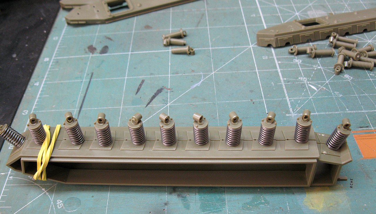
| Installing the springs on the suspension legs... Start with 3 or 4 sets and hold in position by spring pressure... |
 |
| Then "close" the sponson, but not paste yet. Use a rubber band to keep the thing together... |
 |
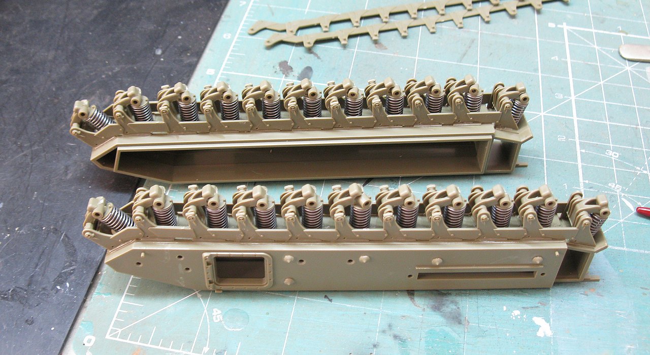
| Go fitting leg after leg, being careful not to disassemble the previous one... |
 |
| With all the suspension legs in place, it's time to start gluing... |
 |
| Apply glue to the marked depressions (yellow arrows). Be careful not to let the glue run down the legs, as this would prevent them from moving freely... |
 |
| Notice the glue mark (yellow arrows). Test the free movement of the suspension legs by rotating them... |
 |
| After 15 minutes of work, the entire inner part of the suspensions is ready, for the two kits... |
 |
| This step is a bit boring, as the pieces are delicate... But, again, work methodically... Gluing the vertical dividers, on only one side... If you want to see more details of this step, I suggest a quick look at the other Churchills buildings here, in the Bunker... |
 |
| Suspensions practically ready... |
 |
| Wheels time!!! Again, assembly line!!! |
 |
| Suspensions ready!!! |
 |
| And the suspension sponsons are growing fast, too... |
 |
| Sponsons ready for action. Notice which are parts of two tanks... |
 |
| Building the lower hulls...The weights are for a perfect alignment of the sponsons with the chassis... |
 |
| Closing the upper-decks. I needed to get to this stage to increase the rigidity of the sets... |
Well... now, it's a delicate step: simulating the weight applied to the suspensions by the devices installed in these Funnies. Both, the AVRE SBG assault bridge and the AVRE Fascine have an overhead installed in the forward portion of the tanks (the SBG more intensely). Therefore, I will simulate this concentration of weight in the bow portion of the tanks, compressing the suspensions. For this, I will apply weights and/or adhesive bands to simulate overloading the front suspensions and glue the suspensions with this "overload" aspect.
 |
| The Churchill AVRE SBG chassis, with weight Notice the front wheels crushed by the weight... |
 |
| I glued the suspension legs in the desired position with self-curing dental acrylic, which I applied with a brush to the inner portions of the hull... |
 |
| Internal view of suspension legs glued to the hull in the desired position with self-curing dental acrylic. Left view |
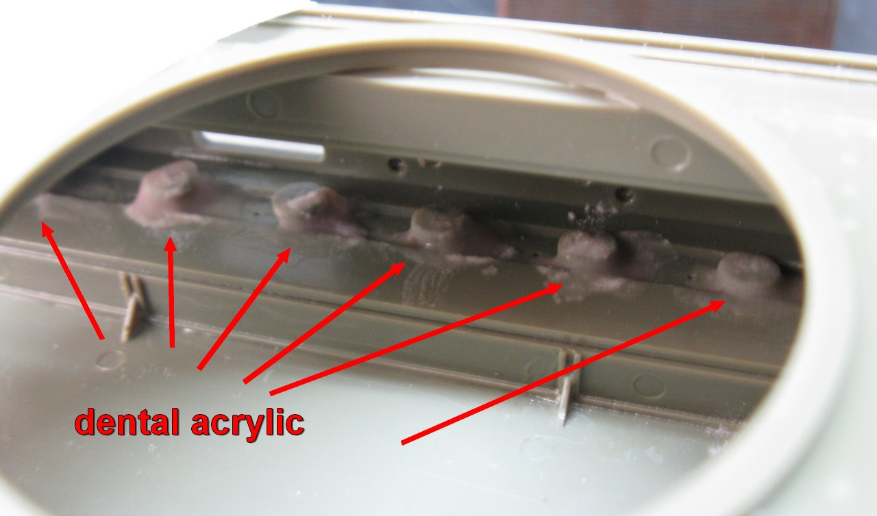 |
| Internal view of suspension legs glued to the hull in the desired position with self-curing dental acrylic. Right view |
 |
| The two hulls, with suspensions "burdened" by weight... |
 |
| In addition to the suspensions "buried" by the weight, I'm going to put counterweights inside the hull, in the most aft portion possible, to counterbalance the weight of the bridge and the fascine. |
I paint some blocks of metal, to prevent future corrosion, to serve as ballast on the back of Funnies Girls. In the real case the Churchill's weight (40 t) is more than enough to balance the 4 t. of the bridge, even being in balance, projecting itself in the bow of the tank. but in the kit, the bridge weight lever can destabilize the kit. The solution is to use a ballast... See the diagram, below:
 |
| Our elephant (ballast) will balance the weight of the cantilevered bridge. This will stabilize our kit... |
 |
| I'm going to use the same solution for the SBG and the fascine only the SBG needs more ballast, as the bridge is projected further ahead of the hull, multiplying the mass action... In the pic, the left ballast is for the SBG and the the smaller one ( right), is for the fascine |
 |
| Testing the adaptation of the ballast. It will be placed as far back as possible, inside the hull... |
 |
| I will apply epoxy glue in the marked positions... |
 |
| Quick-drying epoxy glue. The Invention of the Gods!!! Chuck is happy with the solution... |
 |
| The two ballasts glued to the hulls. Adhesiveness is extremely strong, by Crom!!!! |
While the ballast completes drying, I will build the bridge in parallel, to get an idea of the final weight of the piece... if necessary, there is room for more ballast... But when checking the Resicast parts, I discovered some small problems...
 |
| Two diagonal braces were fractured, beyond the base of one of the bridges... But no big deal... These things are normal in resin kits... |
 |
| Watch your precious fingers... |
With the parts clean, we're going to use a 1.2mm T-shaped Plastruct, which Resicast supplies us...although I'm almost certain that the quantity supplied in the kit is insufficient...but come on... one problem at a time...
 |
| The single Plastruct T-rod from Resicast and the new parts in position... Chuck is happy...for now!!! |
 |
| The sides of the bridge are now fixed and cleaned... |
 |
| Reopening all the holes... |
 |
| This stage is pretty boring...be careful not to break anything, because the pieces don't have extras... |
I suspected the amount of the T-rods... The Resicast sent one... it would take at least three... Good thing I have some of these gems in stock...
 |
| I love my Plastruct's styrene parts stock |
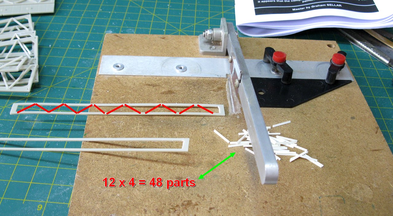 |
| 48 pieces are needed to "braid" the beams... |
Gluing each one with super glue. Good thing there are markings on the pieces that indicate the position of the rods. Very important to glue a piece in the center, to prevent deformation during gluing...
 |
| Sewing the rods... |
 |
| Good job!!! |
After the super glue is completely dry, remove a small portion of the pieces, so that 1 mm from the edge is free of any obstacles, to allow gluing. I removed this portion with carborundum disk in my Dremel. Piece of cake!!
 |
| Making room for future adaptation of the piece... |
 |
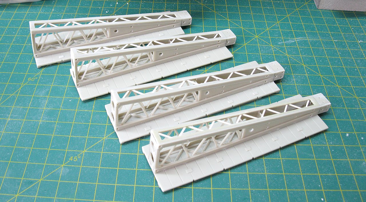
| Now, let's start assembling the 4 segments that make up the bridge. The position of the crossbars must be the same, following the instruction booklet... |
 |
| Hmmm...part number 4 came out really weird... |
 |
| I find it easier to abort the use of these resin parts and make new ones, with 0.2mm thick plasticard |
 |
| Much better...I think you agree too, don't you Chuck??? |
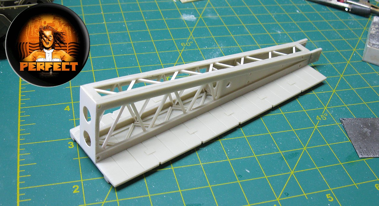 |
| She's perfect!!! |
 |
| Twice perfect!!! |
 |
| Now, let's do the last two parts... |
 |
| Bingo!!! |
Now, an up-grade: we're going to replace some rough resin parts with metal locking hooks, as it would be on a real bridge...
 |
| Making metal hooks... Keeping the halves together and stable, forever... |
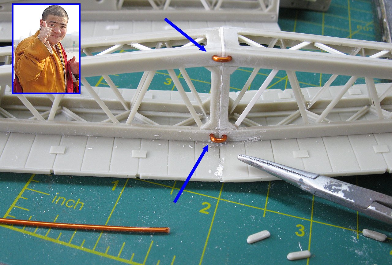 |
| Much, much better!!! |
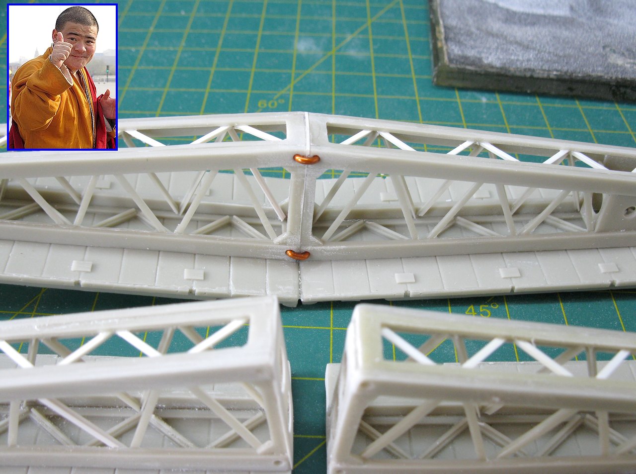 |
| Now, let's glue the other two halves together... |
 |
| Here, alignment is crucial!!! |
 |
| Using plastic clamps so that the two halves are identical and, with that, we can glue the other half perfectly "mirrored" |
 |
| Everything perfectly aligned...now, it's time to "sew" the last pair with super glue!!! |
 |
| Super glue drying and.... |
 |
| ...both bridges at the same height and alignment. Now, just place the metal clamps and continue the construction... |
 |
| Putting all the parts together, carefully and never neglecting the alignment... |
 |
| And the SBG assault bridge is almost ready!!! Field test!!! |
 |
| SBG assault bridge belly view... |
Continuing the construction of the bridge, let's go to the details of its ends... This part is one of the key stages of this construction, as it is through these parts that the bridge connects with the tank. Here, the construction must be strong and aligned, otherwise the bridge could break and/or be crooked, which would destroy the whole project...
These connecting pieces (so-called nose fixation plates - C1 and C2) are extremely thin and fragile in resin. Thankfully, Resicast provided metal parts (P2) to reinforce these important components.
 |
| The very important nose fixation plates - C1 and C2, with the metal reinforcments (P2), ready to install. The P3 metal parts are just details of the set. |
These parts must be aligned both horizontally and vertically. As there are no orientation markingss in the kit, I used a plastic rod to be able to visualize this alignment in a "spatial" way... I made a collage with a micro-drop of superglue until the correct alignment was verified and, only then, I "sewed" the pieces onto the bridge with lots of superglue.
 |
| Visualizing the horizontal alignment of the pieces. These parts will be responsible for coupling the bridge to the tank... Perfect!!! |
 |
| Visualizing the vertical alignment of the pieces. These parts will be responsible for coupling the bridge to the tank... Again, perfect!!! Now, glue everything tight... |
Another problem of the fragility of the pieces from the scale and the material used... This time, the two pillars that will receive the "A" frame, which will keep the bridge in balance, through the steel cables. In the kit, these parts will receive a nice load of traction and the resin is almost transparent here...
 |
| See the resin pillars and their position in the equipment... A crack here is almost certain... |
 |
| The two masts that will form the "A" that will support most of the bridge's weight... |
 |
| Reinforcing the two cruciform posts with acrylic dental resin. I sacrifice a little fidelity, but gain in robustness!! Crom count the dead!!! |
 |
| The "A" frame in position, in dry-run... With the reinforcements, I feel a little more confident... Conan was pleased!!! |
 |
| Adding details at the other end of the bridge... Hmmm... a small piece was broken... |
 |
| ...but nothing a little whimsy can't fix... |
 |
| The front portion of the bridge almost finished... |
 |
| Same problem with cruciform poles... same solution!!! |
While the bridge rests, let's take care of the hulls... As this girl is going to make a long trip, I decided to reinforce the gluing of the ballasts, placing beams made with spue over the metal, to prevent any movement or displacement... The images speak for themselves: superglue and dental acrylic, as parts of the structural reinforcement. Detail: the sprues are introduced and glued through the air inlets, which will later be sealed with their respective air filter boxes. See below:
 |
| Measuring the sprues: the flat portions were specially chosen, as they are more reinforced... |
 |
| The sprues glued in position, not affecting the bonding of future air filters... |
 |
| Internal view of reinforcements. With this, the ballast does not move even in an earthquake with magnitude 8, in the Richter scale!!! |
 |
| While the acrylic dries, let's take care of AVRE racks. A work of a Tibetan monk!!! |
 |
| The Mk.III AVRE hull almost ready... |
 |
| Rear view |
 |
| We are almost in the final stages... |
The engine door locks are made of plastic, very thin and fragile. There are 3 burrs to remove on each of the 4 parts... You know what: it's easier (and much better) to simply replace the plastic parts with parts made of copper wire, in the correct thickness and shape. .. See the photos below:
 |
| The plastic and the metal locks... The lads are satisfied and happy!!! |
 |
| Much, much better!!! |
 |
| The quadrangular angled turret, typical of the Mk. III left front view |
 |
| The quadrangular angled turret, typical of the Mk. III right front view |
 |
| Testing (but not fitting) the turret on the chassis... left view |
 |
| Right view |
Now, a part that must be done very well: the installation of the two arms that support the bridge. This piece must be perfectly aligned, otherwise, the bridge would be crooked and the kit, totally horrible!!!
 |
| The two arms that support the bridge. The bridge pivots on the two axes indicated by arrows. left front view |
 |
| The two arms that support the bridge. The bridge pivots on the two axes indicated by arrows. right front view |
 |
| Alignment of parts and shafts looks perfect... |
 |
| Fitting the bridge in the front arms... Notice the axles that support the bridge... left view |
 |
| Fitting the bridge in the front arms... Notice the axles that support the bridge... right view |
 |
| An overview of the bridge installed on the tank... Perfect!!! It was great to have the ballast installed in the rear of the tank... the tipping effect of the bridge is considerable... |
 |
| An overview of the bridge installed on the tank... Rear view. The cables are only temporary... |
 |
| The weight effect on the suspension...I liked it!!! |
Now it's time to build the bridge winch, which is installed in the Churchill's rear upper deck. The resin parts are very fragile and with some warping... Hmmmm... I think I'll go for something radical... These resin parts are really not convincing me... I think I'll replace everything by Plastruct ...
 |
| The resin parts (red arrows) and Plastruct rods (green) |
 |
| The resin parts (red arrows) and Plastruct rods (green), cut to the correct measurements... now, it's time to glue everything!!! |
 |
| Gluing the details in the parts... |
 |
| And building the manual winch. The two vertical pieces seem a little thin to me, too weak for the winch... |
 |
| I decided to exchange for pieces a little more robust, more compatible with the set.... Much better!!! |
 |
| Everything perfectly squared!!! |
 |
| Final details on the winch... The crankshaft axle was made with strong steel wire!!! |
 |
| And the winch installed on top of the Churchill's rear deck. I removed the additional bogies from the rear fenders, as the thing was a little tight for handling the cranks... |
 |
| Rear view |
 |
| Left view... The end is near!!! |
Now, let's start the most interesting phase, which is the historical research, with its markings and painting. My girl will be Normandy, so we go with green for the tank and bridge in light gray, as we saw in the historical text above...
 |
| Primer in green... left view |
 |
| Right view |
 |
| Light gray in the bridge... first layers... right view |
 |
| left view. |
And now, the most interesting part: as I chose to build an AVRE SBG in the Mk.III version, the options were scarce, but thanks to Peggy, the hot librarian from Kojak Research Team...
 |
| Peggy, the librarian of Kojak's team... |
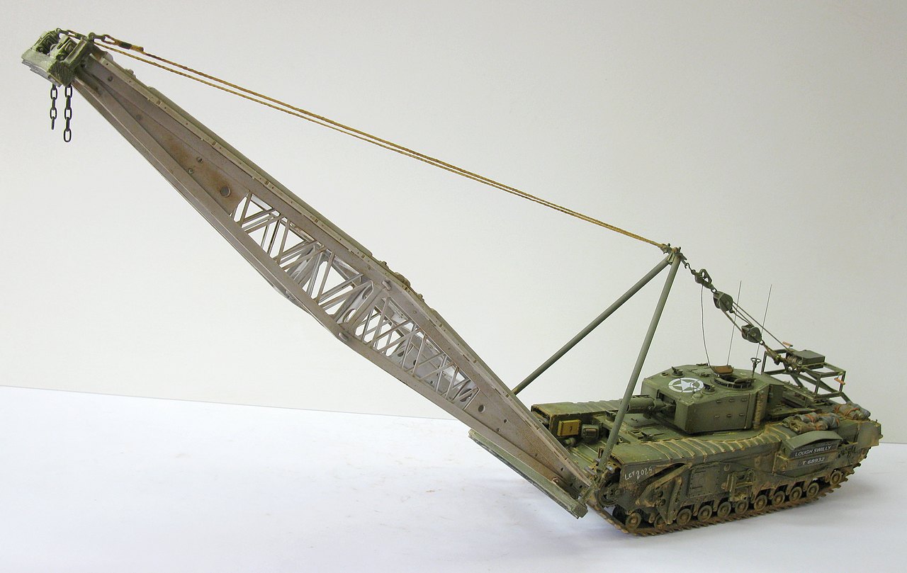
...we found this true historical reference: Churchill Mk.III AVRE SBG Assault bridge "LOUGH SWILLY" (T 68932), from 82nd Assault Squadron, 6th Assault Regiment, 79th Armoured Division, commanded by Lnc Sgt. Pinks, who landed from LCT 2025 on D-Day, Normandy, June 6, 1944.
 |
| Color profile of Churchill Mk.III AVRE SBG The SBG devices have been omitted for ease of viewing. |
Well, after this fantastic work by Peggy, the problem is now the markings. The solution for this is to print the decals, after making the art of the drawings. As always, the big problem is white, which laser printers don't (yet) print. And if I print the colors only on the transparent decal, the colors are "faint", with no contrast. The solution is to provide solid white decals and print the colors on these decals. Of course, small white letters and numbers are impossible to solve by this method, but luckily the tanks of the 6th Assault Regiment had their names (all beginning with an L) and census numbers inscribed in white rectangles. Bingo!! Fortune smiles on those who are bold!!!!
First of all, look in the decals' junk box: I have the 79th Armored Division's Bullhead and the Allied Star, but no AoS from the 6th Assault Regiment, names or numbers... Well, not bad.. Let's draw in Corel Draw the missing marks... See below the print-screen image from the Corel Draw software screen, where I drew the drawings that will be printed on transparent decals and the drawings that will be printed on a solid white decal, to serve as a background. These "backgrounds" are micro-millimeters a little smaller than the colored ones, so as not to interfere with the aesthetics of the decals, after the colored ones are applied over the white ones.
 |
| Print screen of the Corel Draw software This program allows you to obtain the actual sizes of drawings in millimeters when printed. |
After the artwork has been executed and the sizes confirmed, we will print the complete artwork on a simple A4 sheet of paper, to serve as a "bed" for the future printing of the decal sheets...
 |
| A4 sheet of paper. Notice the two "families" of drawings: color (transparent - above) and white (below) |
Once the A4 sheet is printed, I cut out small portions of transparent and solid white decals to position over the already printed designs, securing them at the ends (which will not receive printing) using good quality transparent adhesive tape. With this, we save decal sheets, because the laser printer heats up and if a sheet is too exposed to this heat, it ends up being lost. Don't worry about the sticky tapes: they won't stick or come off, damaging your printer. Re-insert the sheet with the decals into your printer's tray and print again: the print will be EXACTLY where you placed the decal pieces. Simple and efficient!!!
 |
| The A4 sheet whit parts of decals secured in position by adhesive tapes |
And, after printing everything, it's time to cut the decal as close to the art as possible (that's the biggest problem...) and apply it in the kit, after a treatment with gloss varnish or Future (Pledge), to avoid the infamous silvering... Sorry ladies and gentlemen, I didn't photograph the green tones on the vehicle, but I swear I did!!!
 |
| I follow a method: first I apply all the background decals and then the transparent-colored ones. notice the size correlation between them... Front view |
 |
| Applying the white background decals. The Bull's Head is AFV Club. |
 |
| Backgrounds to vehicle's name and census number right side |
 |
| Backgrounds to vehicle's name and census number left side |
Now, you ask me: why all this layering complication? Why don't you print straight in white and that's it??? It's just that, when cutting the white decal, INVARIABLY a white border stands out, leaving the markings simply horrible!! Just for that!!!
 |
| Our girl now has a name and a social security number!!! I salute you, Miss Lough Swilly - what a beautiful name!!! Perfect finish!! left side |
 |
| Lough Swilly - Churchill Mk III AVRE SBG Perfect finish!! right side |
 |
| Front markings... Don't worry: the wrinkled disappears when the Pledge dries... |
 |
| Lough Swilly almost ready!!! 3/4 left view |
 |
| Lough Swilly almost ready!!! Notice the LCT number written with chalk on the front fender left view |
 |
| Lough Swilly - right view Notice the LCT number written with chalk on the front fender |
 |
| Lough Swilly - rear view Notice the shades of green painting... Now, it's Bridge time!!! |
 |
| Installing the "A" type posts and mooring cables. I used a cable without "hairs" for this job. Notice the metal block on the bridge stabilizing the set while the moorings are made. See also the "A" frame being tensioned by the rubber band, tied to ballast blocks, on the bench.... |
 |
| The suspension cables of the bridge, in closer approximation.... |
 |
| The angle of the bridge was fixed at 40°, to facilitate the exposure of the model... |
 |
| As the bridge is relatively heavy (100 grams), I replaced the kit's resin terminals (extremely fragile) by the cable itself bent and tied. We have to avoid accidents.... |
 |
| The same type of procedure in the A frame lashings... Much stronger!!! |
 |
| and while we're talking about strength, how about steel pins on the A frame bases??? |
 |
| Another strengthening surgery: replacement of the eyelets (in fragile resin, in blue) of the pulleys by metallic ones (red)... Again, resistance is everything!!! |
 |
| A substantial difference!!! Much better!!! |
 |
| Tension cables between winch and reverse pulley. Notice the metal details, made with jewelry chain links (green) and copper wire (red). |
 |
| The purpose of replacing some resin parts by metallic ones is to ensure that the bridge does not fall and break!!! The steel hook is to allow the disassembly of the bridge to transport the kit. |
 |
| Testing the bridge suspension system... Things are going very well... |
 |
| A very annoying part was the passage of the cable of manual winch through the pulleys. The thread provided by Resicast was kind of hairy.... |
 |
| The most difficult and complicated thing was to pass the thread through the winch drum (red arrow). It took the patience of a Tibetan monk to do this, with tweezers!!! |
 |
| But this patience work resulted in a stronger pulley system! These "hairs" will be eliminated with a thin layer of PVA glue diluted in water, applied with a brush on the threads... |
 |
| Another thing it replaces were the winch cranks: the ones provided by Resicast were very fragile: with leftover PE and copper wires, I got these more robust cranks, without corrupting the scale of the model. |
And after painting all these details and giving the model a "bath" of weathering, I consider the project ready: With you, the Churchill Mk.III AVRE SBG Assault bridge "LOUGH SWILLY" (T 68932), from 82nd Assault Squadron, 6th Assault Regiment, 79th Armoured Division, commanded by Lnc Sgt. Pinks, who landed from LCT 2025 on D-Day, Normandy, June 6, 1944.

 |
| Churchill Mk.III AVRE SBG Assault bridge "LOUGH SWILLY" 82nd Assault Squadron, 6th Assault Regiment, 79th Armoured Division D-Day, Normandy, France - June 6, 1944. |
 |
| Churchill Mk.III AVRE SBG Assault bridge "LOUGH SWILLY" right front view |
 |
| Churchill Mk.III AVRE SBG Assault bridge "LOUGH SWILLY" right front view |
 |
| Churchill Mk.III AVRE SBG Assault bridge "LOUGH SWILLY" right front closer view |
 |
| Churchill Mk.III AVRE SBG Assault bridge "LOUGH SWILLY" right view |
 |
| Churchill Mk.III AVRE SBG Assault bridge "LOUGH SWILLY" right rear view |
 |
| Churchill Mk.III AVRE SBG Assault bridge "LOUGH SWILLY" right rear closer view |
 |
| Assault bridge - right view |
 |
| Churchill Mk.III AVRE SBG Assault bridge "LOUGH SWILLY" left front view |
 |
| Churchill Mk.III AVRE SBG Assault bridge "LOUGH SWILLY" left front closer view |
 |
| Churchill Mk.III AVRE SBG Assault bridge "LOUGH SWILLY" left view |
 |
| Assault bridge - left view |
 |
| Churchill Mk.III AVRE SBG Assault bridge "LOUGH SWILLY" with Kojak. |
 |
| Churchill Mk.III AVRE SBG Assault bridge "LOUGH SWILLY" left view - without assault bridge... |
 |
| Churchill Mk.III AVRE SBG Assault bridge "LOUGH SWILLY" 82nd Assault Squadron, 6th Assault Regiment, 79th Armoured Division D-Day, Normandy, France - June 6, 1944. |
Ladies and gentlemen, this project
was a real challenge...and a delight!!!
 |
| See you, soon!!! |