
Ladies and Gentlemen...
Today we will see one of the pioneers in the long and glorious lineage of British armored vehicles: Let's talk about the first vehicle built by Vickers...It's Vickers Infantry Tank No.1 time!
 |
| Vickers Infantry tank n°1- 1921 modified from IWM MH 8756 photo |
History:
The Vickers Infantry Tank No.1 stands as the inaugural British tank equiped with an armed turret with 360° traverse. Although Little Willie had this design in mind, Vickers No. 1 was the first fully functional British tank to feature this important feature.
 |
| Little Willie notice the space at the top of the hull for the future rotating turret. |
The Vickers Steel Foundry Company (Sheffield) began to become one of the largest weapons and defense material manufacturers in the world in the late 19th century. In 1897, they purchased Maxim Nordenfelt Guns and Ammunition Company, propelling the foundry to leading positions in the small arms and artillery markets. Slowly, Vickers expanded, acquiring shipyards and naval artillery companies. Until in 1919, they purchased the Metro-Cammell (Metropolitan Railway Carriage and Wagon Company), which, in addition to manufacturing railway carriages, had been manufacturing tanks since 1917.
Vickers Limited rise to major company status was strongly linked to two figures: Sir George Thomas Buckham and Sir Arthur Trevor Dowson. Buckham was Vickers' chief designer, responsible for managing and developing new types of weapons produced by the company. And Dowson was the dynamic director who controlled Vickers as a whole from 1906 to 1931. Almost all of Vickers' new armaments developments were patented by these two individuals.
 |
| 1914 advertisement in Jane's showcasing Vickers' extensive arms manufacturing capabilities |
During the First World War, Vickers, through its subsidiary Wolseley, was involved in the production of armoured cars, but had no direct involvement in the development of tanks.
 |
| Wolseley First Admiralty Open type armoured car entering Antwerp with RN Naval Brigade - October, 1914 |
 |
| Wolseley armoured car CP type - 1915 |
However, at the beginning of the 1920s, Vickers realized the opportunity to introduce itself to the light tank market, which had been completely forgotten by the United Kingdom. This attitude allowed other nations to take the lead in the development of light tanks.
In the beginning of 1921, the French, Americans, Germans, Italians, and even the Soviets with their Renault Russian tank had surpassed the British in this domain. Consequently, British tank building found itself in the position of playing catch-up unexpectedly. However, it is worth noting that this situation was not overly concerning. In retrospect, only the Italian FIAT 3000 and, to some extent, the German Leichter Kampfwagen II (LKII) met the new mobility requirements at the start of the 1920s.
 |
| FIAT 3000 model 21 - early |
 |
| Leichter Kampfwagen II - LK-II (light combat vehicle) |
Other vehicles considered light tanks were desperately slow, most often underpowered and very lightly armed. So the Vickers Company took charge of these efforts, with Sir George Thomas Buckham, Vickers' chief designer, leading the way.
%20cut%20paper%20silhouette,%201923%20-%20National%20Portrait%20Gallery,%20London.jpg) |
Staff of Messrs Vickers, Sheffield - from left to right - Sir George Thomas Buckham; Sam Robinson and Colonel E.A.P. Hobday. Cut paper silhouette, 1923 National Portrait Gallery, London |
In 1921, Vickers Works, located in Erith, a region in south-east London, secured a contract which guaranteed the design and construction the prototypes of 3 light tanks, but with a very loose delivery schedule. The initial Vickers tank, being the first of its kind, was constructed with a "rhomboidal" hull design, adhering to conventional practices. This particular configuration was necessitated by the requirement to surmount hard obstacles. It is noteworthy, however, that the hull was the sole characteristic shared between the new tank and the heavy "rhomboids" employed during World War I.
 |
| Rhomboidal: the typical shape of British tanks in WWI |
First prototype:
The first vehicle was completed in December ,1921 and was sent to Farnborough, where a research facility was established at the 2nd Battalion of the Royal Armoured Corps.
 |
| Vickers Infantry tank n°1- 1921 font: IWM MH 8756 |
First of all, the Vickers Tank No.1 showed a notable reduction in size compared to the British tanks utilized during the Great War. The driver's station, previously afflicted by severely limited visibility, underwent a complete transformation: in contrast to the previous tanks ergonomy, the driver's position in the Vickers Tank No.1 offered enhanced comfort and functionality.
 |
| Driver station: the best place in the house!! |
Weighing less than nine tons, the tank was equipped with a 6-cylinder Wolseley engine of automotive origin.
 |
| A six-cylinder Wolseley automotive chassis notice the engine |
Notably, despite its rhomboidal hull, the tank's crew was housed in the fight compartment, positioned in the front of the vehicle, with the engine and transmission compartment in the rear, isolated from the crew compartment by a armored division. This arrangement generated a huge improvement in the operational performance of the crew, which no longer had to deal with the deafening noise, heat and gases from the engine.
 |
| The fighting compartment (blue) in the front of the vehicle, insulated from the engine compartment (red) This division of spaces generated a huge gain in the crew’s operational productivity |
The tank employed a Williams-Jenney hydraulic transmission, a technology used since the "rhomboid" era, but which in this tank did not prove to be very reliable, generating many problems in field tests. The tracks featured a new and more durable construction, incorporating wooden pads, to increase traction.
 |
| The Vickers Infantry Tank No.1 in trials, at Farnborough fields. Notice the the rear engine compartment covers open. It looks like the Williams-Jenney hydraulic transmission has failed again... |
But Vickers' biggest innovation with Tank No.1 was the placement of its armament: surprisingly, the British chose to install the armaments inside a full-rotating turret, which even had a cupola for the Commander. Similar to the medium and heavy tanks of World War I, the Vickers design adopted a "Female" version configuration, equipped exclusively with machine gun armament. Three .303-inch Hotchkiss machine guns were mounted on ball mounts, significantly increasing the tank's firing maneuverability through the turret's full 360° rotation. The turret bearings were located outside the hull, a design feature that was later used on other Vickers tanks.
 |
| Turret details of Vickers No.1 tank: Red - 0.303 in. Hotchkiss mg and its ball mounts (3 in total) Green - one of 3 sets of turret bearings, installed externally. Blue - Commander's cupola, with direct vision slots. Purple - The two flat hatches of the Commander's cupola |
As we saw earlier, Tank No. 1 was considered ready for trials near Farnborough in December 1921. It is worth noting that in the same year, a research facility was established in the area, utilizing the 2nd Battalion of the Royal Tank Corps as its foundation, subsequent to its relocation from Dollis Hill. This facility was later renamed the Mechanical Warfare Experimental Establishment (MWEE) in 1928.
In field testing Vickers tank no.1 was assigned identification number 6.
 |
| The Vickers Infantry Tank No.1 in trials, at Farnborough fields. Notice the number 6 in the hull side and, again, the engine doors open, indicating mechanical problems |
The testing phase produced mixed results as the Williams-Jenney hydraulic transmission, known for its unpredictable behavior, once again exhibited its temperamental nature. Furthermore, the tank's engine proved to be relatively weak. Consequently, at the beginning of 1922, the vehicle underwent changes, incorporating an 80 horsepower Lanchester 40 petrol engine. As a consequence, the specific power underwent a notable increase, leading to an increase in speed of up to 24 km/h. Consequently, the Vickers Tank No.1 emerged as the fastest among the "rhomboid" tanks.
 |
| The Vickers Infantry Tank No.1 in trials, at Farnborough fields. rear view - notice the tracks, with wood pads. |
In a general summary, the Vickers Tank No.1 represented a relative departure from the paradigms of previous tank designs, presenting notable advances in relation to size, driver position, positioning and compartmentalization of the engine and transmission, tracks and, mainly, the adoption of an armed turret with 360° drift. Although still presenting the rhomboid layout of WWI tanks and the weak armament consisting only of machine guns, we can say that the Vickers no.1 was the first of the tanks with "modern" characteristics of the British.
 |
| Although still featuring a rhomboid appearance, the Vickers no.1 was a bold innovator with its internal ergonomics and full-rotation turret. |
Second prototype:
In July 1922, Vickers began work on a cannon-armed version of tank No. 1, called Vickers Tank No. 2. This prototype had practically all of the design of its predecessor, with small changes like the side armored skirts, the engine cover in the rear of the hull and the most important change, characterizing the vehicle as a "Male" version: the replacement of the machine guns by an Ordnance QF 3-pdr 2 cwt Vickers (L40) gun.
 |
| Vickers Infantry Tank No.2 in trials, at Farnborough |

This heavier weapon was installed in the front portion of the turret, slightly modified in relation to tank no.1. This new turret did not feature machine gun bal mounts or a commander's cupola. For close defense, the tank had, at the rear of the turret, a ball mount for a .303 Hotchkiss machine gun., aligned with the cannon, but installed a little higher, allowing anti-aircraft use.
 |
| Main differences noticed in Vickers No.2: red - Ordnance QF 3-pdr 2 cwt Vickers gun. green - absence from the Commander's cupola blue - ball mount with .303 Hotchkiss machine gun |
In the early summer of 1923, Tank No. 2 was sent to field trials at Farnborough, being received by the British military with much skepticism. The new tank had very similar performance to Tank No. 1. The increase in power of the Lanchester engine was practically canceled out by the greater weight of the new version, which almost reached 10 tons. An improvement in agility and maneuverability on off-road terrain was noted, but very small. The transmission was still fragile and inconsistent, generating numerous interruptions in testing. But the most serious thing was that the new engine began to show a constant tendency to overheat. This was a really serious problem, as the British military planned to use these vehicles in India, as colonial tanks..
 |
| Vickers Infantry Tank No.2 in trials, at Farnborough. Notice the engine access panels open, at the rear of the vehicle. The engine overheated constantly... |
 |
| Vickers Infantry Tank No.2 in trials, at Farnborough, with the engine access panels open at the rear of the vehicle. The engine overheated turned into a nightmare. |
Consequently, after completing the tests and evaluating the performance and reliability results, the two tanks were considered unsuitable and therefore rejected. We can say that the failure of these vehicles was due more to the mechanical options available at the time than to any flaw in the general design of the project, which we can consider as correct. The final fate of tanks n°1 and n°2 was scrapping, which took place around 1927-28. It's a pity that the first tanks manufactured by Vickers have not been preserved.
Third prototype:
At the end of 1922, with work on prototype tanks No. 1 and 2 becoming so problematic, it began to become clear to Vickers that their infantry tank would not be approved for mass production.
In a risky move, Vickers engineers decided to completely modify the concept of the third prototype, building a truly new vehicle, abandoning the old theories of the rhomboidal shape and primitive suspensions. They decided to build an tracked carrier for the QF-18 pounder (84 mm) field gun: the Vickers 18 pdr. Transporter.
| Vickers 18 pdr. gun Transporter (Vickers prototype no.3) in the Vickers plant - 1923 |
 |
| QF-18 pounder field gun of the Royal Field Artillery in action. Second Battle of Arras, France - 29 April, 1917. font: IWM Q 5811 |
This vehicle had nothing in common with the Vickers No.1 Infantry Tank. Rather than an evolution of the concept, it was like a leap forward compared to any other vehicle in development in those days. The main modification was the change in suspension: from a system of springs with very little travel, almost semi-rigid, to a really effective suspension, with bogies with two wheels acting on vertical helical springs. In addition to the new suspension, a new set of tracks was developed, with more grip and traction to the movement.
| Vickers 18 pdr. gun Transporter (Vickers prototype no.3) in the Vickers plant -1923 Notice the suspension and the rear folding door |
As the vehicle was a little lighter, the 73 hp Wolseley gasoline engine from Tank No. 1 was used, with the engine being installed in the front portion of the hull and the transmission in the rear.
| Front view of Vickers 18 pdr. gun Transporter (Vickers prototype no.3) The engine is placed in the front of the vehicle. |
The 18-pdr field gun would be drawn into the hull through an folding door at the rear, equipped with ramps, and the crew would sit around its perimeter, positioned on benches on the sides of the hull, facing each other.
| Rear view of Vickers 18 pdr. gun Transporter (Vickers prototype no.3) with the assimetrical ramps for the gun in position with the rear door folded. The transmission is placed in the rear of the vehicle. Notoce the gunners seats, facing each other, on the sides of the vehicle. |
The first field tests proved the immense improvement of the new suspension used on the transporter. The transporter, like its siblings, was not put into production and was later dismantled, but its legacy was the new suspension concept, that would be already used on the Vickers Medium Mk.I tank, in 1923 and its more famous brothers, Vickers Medium Mk.II tanks. ..But that's another story...
 |
| Vickers Medium Tank Mk I - 1923 font: IWM KID80 |
Specs:


| Vickers Infantry Tank No.1 | |
|---|---|
| Type | Infantry light tank |
| Place of origin | United Kingdom |
| Production history | |
| Manufacturer | Vickers |
| No. built | 1 x no.1 1x no. 2 |
| Specifications | |
| Mass | 8,75 tons - No.1 9,75 tons - No.2 |
| Length | 5,20 m |
| Width | 2.40 m |
| Height | 2.50 m - No.1 2,10 m - No.2 |
| Crew | from 2 to 4 (Commander, driver and gunners) |
| Armour | 12,7 mm |
Main armament | No.1: 3 x 0.303 in Hotchkiss mg No.2: 1x Ordnance QF 3-pdr 2 cwt Vickers gun (47 mm / L40) |
Sec. armament | No.1: none No.2: 1x 0.303 in Hotchkiss mg |
| Engine | No.1: Wolseley 6 cyl. on line engine, water-cooled 73 hp - petrol. No.1 (late) and No.2: Lanchester 6 cyl. on line engine, water-cooled 86 hp - petrol. |
| Transmission | No.1: Williams-Jenney hydraulic transmission No.2: Lanchester transmission |
| Suspension | bogies with vertical helicoidal springs |
Operational.range | 193 km - road |
| Max speed | 24 km/h |
The kit:
For this interesting project, the kit I used was the 3D printed kit from the Vargas Scale Models Vickers No.1 (#R3D-35-073).
 |
| Vargas Scale Models kit (#R3D-35-073) box art |
The kit is very simple, but with very well printed details. It is made up of two sets of complete suspensions, a chassis and a turret. The kit should be very simple and quick to build...
 |
| Kojak and the new girl from Vargas Scale Models |
The only drawback is that my model came with very clear signs of printing, horizontal lines on the sides of the hull that will be impossible to remove, due to the complexity of the details around it... But I don't think things will be that obvious... .so Kojak and I wait...
 |
| The complete hull. Here, the most evident print marks are on the front portion of the hull, on the tank's curvilinear glacis... left view |
 |
| The complete hull right view |
 |
| Tracks and suspensions, still in its printing cradle |
 |
| The turret with its cupola, waiting in its printing cradle |
 |
| Notice the suspensions separated from the cradle and the turret removed from its cradle as well, exposing the weapons and cupola hatch. |
 |
| Four Hotchkiss (one in reserve), as well as the Commander's hatch. Pointed by the red arrow, a little fracture in the side link of the track... |
 |
| The turret is very well printed and detailed, but the print lines on the flat surfaces of the machine gun stations are a flaw... |
 |
| Here, a small problem with the kit's packaging: the right rear attachment point is fractured... But things aren't as bad as they seem.... |
 |
| With a bar of styrene plastic, a scalpel and some patience, we can fix this in no time... Surgery time!!! |
 |
| The coupling ring will be made with a copper wire of suitable thickness and diameter. |
 |
| A panoramic view of the operating room... |
 |
| That's it...Kojak is completely satisfied!!! |
When gluing the two suspension assemblies, a little trick: apply a minimum amount of superglue (because if any adjustment is necessary, you can detach the assemblies without damaging them...) and try to insert the two suspensions in the same way: like the The holes in the chassis are looser than the pins in the suspensions, I pulled the suspensions down and back, on both sides, in the same way. As a result, both sets were perfectly aligned with the chassis and the ground. With this certainty, I then "sewed" the suspensions to the chassis, with more glue, reinforcing the entire assembly.
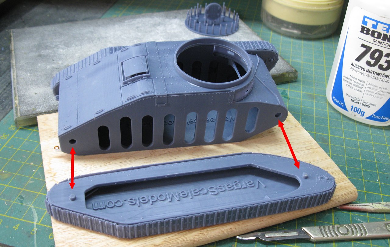 |
| Inserting the suspension sets into the chassis holes: first one side and then the other... |
When I fitted the turret to the chassis "neck", I noticed that the internal diameter of the turret is much looser than the external diameter of the chassis neck, which gives a "loose" appearance to the turret's movement of rotation. After using a caliper, I discovered that the inner diameter of the turret is almost 1mm larger than the outer diameter of the hull neck. The solution is to add a 0.3mm thick plastic strip around the entire outer perimeter of the hull neck. This will increase the outer diameter of the neck by just over 0.7mm, allowing for tighter turret movement. Let's go...
 |
| Choosing a thin plasticard and checking the thickness with a caliper: 0.3mm thick!! |
 |
| After cutting the plastic to the convenient height and length, we will apply our 0.3mm thick necklace to this thin neck, with superglue!!! |
 |
| The 0.3mm thick collar installed on the thin neck of the hull.... Now, let's insert the turret and check the clearance of the rotation movement... |
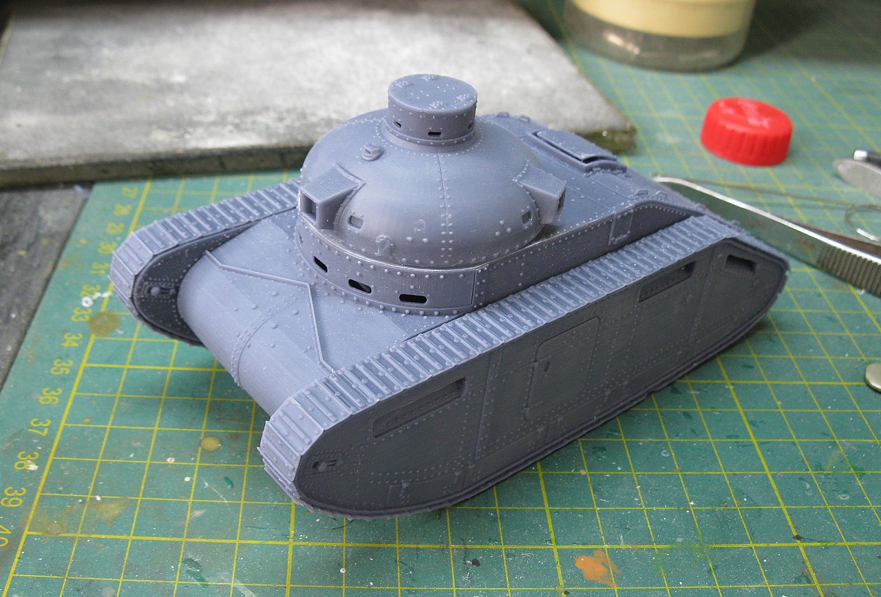 |
| Bingo!! the turret rotates with a certain precision, without gaps or oscillations.... |
 |
| I think this aspect is very steampunk... without a doubt!!! |
 |
| Rear view. |
And now, let's fix the small fracture in one of the track links: let's glue a small portion of thin plasticard (0.5mm) previously cut in the shape of the fracture, to fit and fill in the broken spot...
 |
| The plasticard glued in place. Excesses will be removed after the glue dries. |
 |
| A close-up view of the graft site, with the plastic already cut and sculpted with a scalpel, reproducing the lost surface. The Devil lives in the details, as the ancients said... |
And now, a small criticism (and suggestion) to our dear friend Luis Vargas: you forgot to reproduce the lighting elements of our beautiful girl: she has two front headlights and a rear light. These details are very evident in the (few) photos of the original tank. For these details, I will use an accessory kit from Elf Accessories, which are excellent headlights of different diameters.
AZIZ, LIGHT!!!
 |
| Uops...wrong photo!!! |
That's much better, thank you Aziz!!! See in the pics below:
 |
| Front left and right headlights and the rear light in position, in the real tank. |
 |
| Preparing for plastic surgery!!! Notice the position of the front headlights... |
 |
| Using copper wires as headlight supports... |
 |
| The rear little light was glued on with a simple plasticard base |
 |
| And the headlights installed on our girl!!! Thank you very much, Elf!! |
Well... after this course correction, let's move on to painting. First step: apply several layers of primer, to help the paint adhere and try to mask the infamous horizontal printing lines a little...
 |
| Just after the first layer of primer...after this, at least 4 or 5 more will be applied... all layers very thin, to avoid defects.... |
Well, now it's time for painting. Regarding the colors, after some research, I chose SCC 2 Khaki Brown, a little lightened, to reproduce the brownish tone of English vehicles at that time. The numeral 6, present in the photos, could not be missing. It's time to do the traditional Panzerserra color and marking profile.
 |
| The Vickers Infantry Tank No.1, as seen in field trials at Farnborough in 1921. |
 |
| I used a mix of Vallejo acrylics to achieve these tones... |
 |
| Now, starting the washes, with oils... Man, the printing lines really are a nuisance... left view |
 |
| Washing with oils, right view. |
 |
| Vickers Infantry Tank No.1 - rear view |
 |
| Vickers Infantry Tank No.1 - front view This lady is very fashionable... A true flapper-girl!!! |
And now, let's exercise a little reverse-logic: in the real photos, we can see the presence of the front headlights and nothing else, as the photos are very dark in this region. But an armored vehicle (even more so a prototype...and even more mechanically problematic like this...) SHOULD have front tie-down points (as it had at the rear) to be able to tow and be towed. So here we go: with Chuck Norris' approval, let's add this piece that MUST HAVE existed. I opted for double lashing...it could be simple, like the Churchills, but I followed the trend of the rear of the same vehicle...My spare box came to my rescue...
 |
| Installing tie-down points on the front of the tank: a logical and coherent option. Chuck approves!!! Notice the tracks in gray-metal... |
 |
| And to complete the heresy, tow rings. Come on, admit it: if you were a Vickers engineer in 1921, you would do the same!!! |
 |
| While the towing devices dry, let's prepare the machine guns to fit into the turret's ball-mounts: a small surgical procedure is necessary: small wear on the circular base of each weapon... |
 |
| With wear and tear, a circular piece fits into a rectangular space! This is sooo Apollo 13!!! |

 |
| But back to the Earth: really, this tank is very steampunk!!! |
 |
| This turret is very beautiful!!! |
 |
| The right side of the tank is not that affected by the printing lines... |
 |
| But the left side... Ouch!!! |
 |
| Rear right view of the girl... The right towing point was identical to the original... |
 |
| Rear right view of the girl... Those tank machine guns separated by 120° give the impression that she's always looking at you... |
After several thin layers of Pledge applied with an airbrush, I applied the decals, which were sealed with more Pledge and then, on top of everything, a wash of matte varnish.
 |
| Girl number 6, by Jove!!! left view |
 |
| Girl number 6, by Saint George!!! right view |
 |
| Applying some powder pigments... |
 |
| Our flapper-girl, with her bright little eyes and a chain on her curvy lap... Really, this lady is a bombshell |
 |
| Pigments...and more pigments... |
 |
| The rear red lamp... soooo cute!! |
 |
| What are you looking at??? |
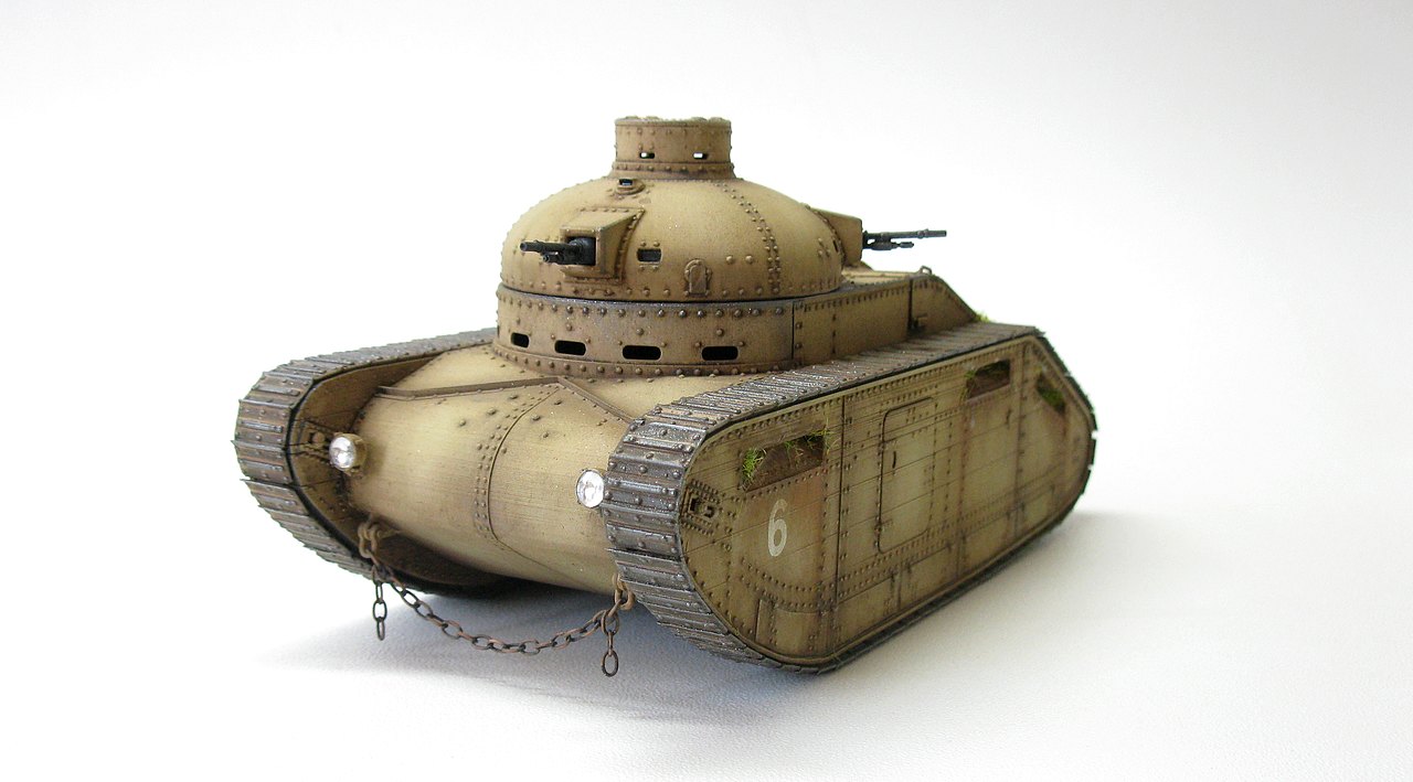
And with a few more layers of pigment and weathering, I can call this flapper ready: With you, the first English girl with a turret armed with 360° of drift and who was very concerned about the well-being of her crew: Vickers Infantry Tank No.1, as it appeared in field trials at Farnborough in the final days of the turbulent and crazy years of 1921.
 |
| Vickers Infantry Tank No.1 - number 6 Farnborough Field Test - late 1921. |
 |
| Vickers Infantry Tank No.1 front left view |
 |
| Vickers Infantry Tank No.1 front left top view |
 |
| Vickers Infantry Tank No.1 left view |
 |
| Vickers Infantry Tank No.1 rear left view |
 |
| Vickers Infantry Tank No.1 rear right view |
 |
| Vickers Infantry Tank No.1 right view |
 |
| Vickers Infantry Tank No.1 front right view |
 |
| Vickers Infantry Tank No.1 rear right view |
 |
| Vickers Infantry Tank No.1 rear right top view |
 |
| Vickers Infantry Tank No.1 with Kojak (very, very proud of this girl!!) |
 |
| From the series "Impossible Encounters", Vickers Infantry Tank No.1 next to a Cruiser A15 tank Crusader Mk I: two authentic English ladies, my good man!!! |
 |
| Vickers Infantry Tank No.1 - number 6 Farnborough Field Test - late 1921. |
 |
| Vickers Infantry Tank No.1 - number 6 Farnborough Field Test - late 1921. |
Well, Ladies and Gentlemen...this project was truly a delight. Vargas kits are generally quite fun to build and it is an opportunity to be able to build kits that are overlooked by most of the "big" kit companies. I would recommend a little more care with the printing of the kits and, perhaps, an upgrade with the missing parts?!?!? Furthermore, thank you very much for following this brief History, my friends...
See you soon!!!