Amis modélistes!!!
The First World War was the stage for the development of new concepts and new tactics, in a strange combination of old philosophies with the new and deadly weapons, which the technological development of the time allowed. Today we are going to meet a vehicle designed by the French that came to be materialized in the form of a prototype and that nowadays may seem crude and totally inadequate, but which was one of the pioneers in the attempt to break the impasse generated by the "Trench War". This time my friends, the topic is about the strange WWI era prototype Char Frot-Turnel-Laffly (armoured steamroller).
History:
The construction of the first armored vehicles in France, as in the rest of the world, was due to many strange and original projects, the vast majority of which did not go beyond the drawing board stage. One of the few that evolved from the idea stage to the materialization of an operational prototype was the so-called Char Frot-Turnel-Laffly, a strange vehicle between the tank and the armored car, although it was actually more of an armored steamroller. This French experimental armoured fighting vehicle was designed and built from December 1914 to March 1915.
As was said before, the immobility of the
trench warfare characterizing the First World War led to a need for a powerful armed military engine that would be protected from enemy fire at the same time, and could move on the extremely irregular terrain of battlefields, smashing through the barbed wire barriers, clearing the way for infantry.
 |
A German machine gun emplacement during World War I.
Library of Congress, Washington, D.C. - USA |
As early as 24 August 1914, the French Colonel
Jean Baptiste Estienne articulated the vision of a cross-country armoured vehicle:
"Victory in this war will belong to the belligerent who is the first to put a 75mm cannon on a vehicle capable of moving on all kinds of terrain." ( Colonel Jean Baptiste Estienne, 24 August 1914 )
 |
Colonel Jean Baptiste Estienne 07 Nov. 1860 - 02 April 1936 |
For the construction of this vehicle, one of the first attempts was made in France on December 1, 1914 by Paul Frot, an engineer of canal construction at the Compagnie Nationale du Nord. Frot proposed to the French Ministry of War a project for the manufacture of an armored and armed "rolling fortress", based on the chassi and motorization of a Laffly steamroller with heavy fluted wheels that was used to compact the soil of the canals.
"This rolling fortress, which only cannon could stop, would force our enemies to adopt another tactic, and anyway would give us a marked momentary advantage." (Letter of Paul Frot to the French War Ministry - Les Sables d'Olonne, 1 December 1914).
 |
Laffly steam roller LT10- DB2
a similar machine was the basis Char Frot-Turnel-Laffly |
This image actually convinced the military to authorize the construction of an operational prototype for field testing. The compactor base was built by the
Laffly Company, at
Boulogne sur Seine using a modified Laffly Type LT chassi and the 7mm armour was made by Corpet Company, at
La Courneuve.
The vehicle was equipped with a box-shaped riveted armored hull, whose lower front and rear surfaces were steeply sloped to allow high entry and exit angles, allowing for better overcoming battlefield obstacles, like trenches, for example. The tractor body was completely symmetrical, with the engine part installed amidships. The control and steering mechanisms were duplicated, located in front and behind, so that the Commander/driver could advance or retreat the machine just by changing positions, as the maneuverability of the vehicle was precarious. The rest of the hull was occupied by fuel tanks, engine cooling system, armament and ammunition.
The vehicle was powered by a Laffly Type LT 4.82 litre 4-cylinders 20 hp petrol engine, and was able to move both forward and backward, with two driver positions, one at the front and the other at the back. It was to be equipped with four
Hotchkiss 8mm M1914 machine guns on raised platforms attached to the compactor chassis: one in front, one in the rear, and two projecting from the front sides for almost 360° coverage.
 |
Char Frot-Turnel-Laffly armoured steamroller
Arches of fire |
Total length was 7 metres, width 2 metres and height 2.3 metres. It weighed a little under 10 tons. It would have been manned by a crew of seven: Commander/driver, two mechanics and four gunners. Speed varied between 3 and 5 km/h.
The Char was tested on 28 March 1915 in the grounds of the Corpet & Louvet factory at La Courneuve, North of Paris, and effectively destroyed barbed wire lines and climbed a 25% slope. But all these tests were performed on relatively easy terrain, with small, smooth obstacles and yet. the vehicle was deemed lacking mobility and stability.
Like the chassis from which it originated, the Frot-Turnel-Laffly vehicle had 2 solid-drive wheels in the rear and a steered front roller, via a wide fork that had a chain-steering system. As solid metal wheels were originally designed for compaction only, on uneven and wet terrain, they had a tendency to slip. To correct this, the rear wheels were covered with a solid rubber tread, which improved but did not solve the problem of lack of traction in more severe situations.
 |
Frot-Laffly roller, tested on 28 March 1915 in France.
The only photo of the vehicle that we can consider reliable,
without extensive retouching.
|
Although it demonstrated ability to crush rolls of barbed wire and destroy obstacles such as metal poles, the Military realized that even on idle terrain, this task proved to be painful for the vehicle, which snorted and swayed as it progressed through the easy terrain. The officers present at the test realized that if the vehicle were transported to terrain similar to that of the Front Line, with its trenches, bomb craters and soft ground soaked and churned up by artillery blasts, it would simply not be able to move in the minimally desired and expected way, becoming useless:
"The trials of this machine have demonstrated that it would not be possible to obtain practically satisfying results from it." ( Letter from Colonel Mourral, Chef de Section technique du Genie, to Paul Frot, Paris, 10 April 1915 ).
 |
A heavily retouched photo of Char Frot-Turnel-Laffly, with the presence of a
75 mm Blockhaus Schneider (BS) cannon at midship, 10 firingports for rifles,
in addition to another machine gun position, with its rotating shield,
at the rear side of the vehicle (in the left, in this picture) |
The armament of the piture above was never actually fitted: the 75mm gun and firingports in the pictures are the result of retouching. The retouched photographs seem to indicate two 75mm cannon, six machine guns and twenty firingports, which would be absurd....
Aftermath:
The project was actually abandoned in favour of the infinitely superior General Estienne's concurrent project of a tank using a tractor base, codenamed
Tracteur Estienne, which was being developed at that time. A few months before, in January 1915, the French arms manufacturer
Schneider & Co. had already sent out its chief designer,
Eugène Brillié, to investigate tracked tractors from the American
Holt Company, at that time participating in a test programme in England. This Schneider program was met with approbation of the French War Ministry, was merged with the Estienne plan, and a production order of 400
Schneider CA1, the first French tank to see the battlefield, was made on 25 February 1916.
The prototype of the Frot-Turnel-Laffly was sold to the United Kingdom, Paul Frot claiming in a letter dated 8 January 1918 that it had influenced British tank design.
Specs:
| Frot-Turnel-Laffly armoured steamroller prototype |
|---|
| Type | barbed wire shredder |
|---|
| Place of origin | France |
|---|
|
| Trials | March 1915 (prototype) |
|---|
|
| Designer | Paul Frot |
|---|
| Designed | December 1914 |
|---|
| Manufacturer | Laffly |
|---|
| Produced | Early 1915 |
|---|
| No. built | 1 |
|---|
|
| Mass | 10 tonnes |
|---|
| Length | 7.00 m |
|---|
| Width | 2.00 m |
|---|
| Height | 2.30 m |
|---|
| Crew | 7 to 9 |
|---|
|
| Armor | 7 mm |
|---|
Main armament | 4 x 8mm Hotchkiss M1914 machine guns |
|---|
| Engine | Laffly Type LT 4.82 litre
4-cyl. 20hp petrol engine
|
|---|
| Fuel capacity | 30 liters |
|---|
Operational range | ? |
|---|
| 3–5 km/h |
|---|
The kit:
For this commission job, the client send to me this kit (with two others...) 3D printed, from Vargas Scale Models. I really hope this kit is in better condition than the Renault FT 17 75BS tank that I built some time ago.
 |
| Vargas R3D-031 kit box art |
But let's get down to business, building this primitive beast!!
 |
Kojak is soooo brave....
Not one or two, but three 3D printed kits from Vargas Models....
Undoubtedly, a guy with cojones!!
Let's have fun!!! |
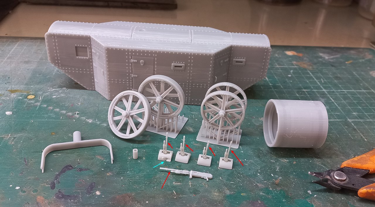
Opening the box: All parts that make up the kit. The hull is like a small hollow "brick", with the bottom already glued at the factory... The beginning of the print, in the vertical direction from top to bottom, is very good, but a little before the waistline, the lines of prints appear... Sanding in these regions no way, because it would destroy all the rivets... Let's see what happens... But at least it's not deformed like the hull of the
Renault FT17 75BS tank that I built, from the same Varga Models, although the print lines are the same.
 |
| Instructions...only one sheet of images |
Too bad all
Hotchkiss 8mm machine guns are warped... Good news is that a spare came, but with a damaged shield... All these details show a lack of care with quality control. The question is, if the printer can print the top first third of the kit perfectly, why not the rest???
 |
All Hotchkiss 8mm MG are twisted...see red arrows
and the shield of one is broken (blue arrow) |
Let's start fixing the Hotchkiss shield: I used self-curing dental acrylic as it's easy to install in larger cavities and it's tough, not shrinking like putty. The negative point is that wear is much more difficult, but Dremel sanding discs are ideal for this...
 |
The big crack filled with dental acrylic....
now, just sand it with Dremel sanding discs.
|
 |
The "wheel set": the steam roller components on the top row and
the rear tractor wheels on the bottom row. Impeccable print from Vargas...whew!!! |
The kit, as you have seen, is very Spartan... And kits of this type always awaken ideas for improvement in Kojak... Let's go to battle!!!
The tractor wheels fit into notches on the chassis (red arrows below...) and must be glued in that position. When we looked at the fittings ( perfect, by the way...), the idea came: why not leave the wheels moving, to make painting easier and add a small upgrade?
 |
| The rear wheels in position: the fittings are perfect. Well done, Vargas!! |
Let's try to do this: my idea is to put small pieces of plasticard in the upper portions of the sockets, locking the axles in their positions. Locking is the way to say, because they must remain rotating, freely... And, above all, a small layer of dental acrylic to reinforce the bonding... See the diagram and the final results below...
 |
The rear wheels turning... The greatest care is
that the glue does not reach the axles... |
Time to build the steamroller... Once again, the fittings and printing are perfect. Unfortunately, I won't be able to make the steamroller rotate freely on the fork, because the kit is a little heavy and I think the possibility of the fork breaking with the weight of the model is very high. My intention is to make a support between the fork and the roller to dissipate the energy of the kit dough more safely...
 |
| The steamroller after building... |
According to the instructions, the roller should be glued in a certain position... but Kojak has the Devil in his body and thought about making the roller have a rotation capacity in the directional direction, so we can give a more real image to the model...
When we insert the roller + fork in its position and turn it, we notice that the top of the fork "scrapes" the fitting base (long red arrows below, in the photo), as it is not flat, but conical... The idea here is to make a "washer" to serve as compensation for the difference in height of the base, so that the fork rests on the axle when turning and does not scratch the base... The diagram below exemplifies the whole story with images...
 |
The base of the roller being scratched by the fork and
a schematic profile drawing of the whole thing... |
The washer (blue arrows in the pic below) made of 1mm thick plasticard, inserted into the root of the fork axle, to free the fork frame from scratching (red arrows) the fork rotation support base...note that I installed a plasticard "hub" between the roller and the base of the fork to correct a small "warp" in this part and reinforce the fork, as the kit is massive (and heavy), and the fork can break...
 |
The washer (blue arrows) made of 1mm thick plasticard, inserted
into the root of the fork axle, to free the fork frame from scratching (red arrows)
the fork rotation support base...Notice that I installed a plasticard "hub"
between the roller and the base of the fork to correct a small "warp"
in this part and reinforce the fork |
And now, the trick part: When inserting the axle of the fork in its receptacle, the tip of the axle comes out of the base, being visible through the large opening of the frontal machine gun, in the bow of the vehicle... When we turn the set fork + roller, the "sharp" edge marks the axis, allowing a perfect view of where the base ends (see the yellow circle, below). With this marking defined, we can drill the axle (red point in the top of axle, in the diagram, below...) to pass a resistant locking pin that keeps the fork in place, allows its rotation and can be introduced through the Commander's frontal "slithole". Easy, isn't it?!
 |
| Photo of roller + fork set, with the horizontal marking visible... |
 |
The top of the axle, with the hole made,
in the diameter of the pin that will be used... |
 |
The real thing, seen through the Commander's frontal slit.
This is what I call complicated surgery... |
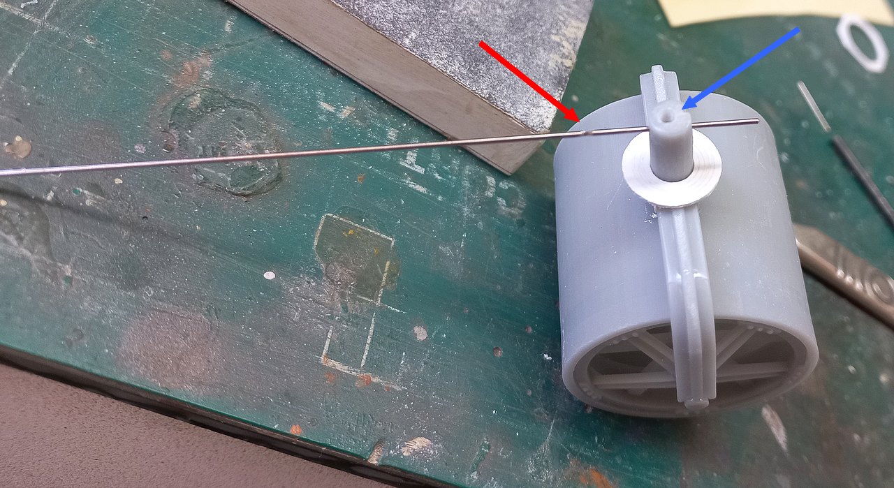
With the hole for the locking pin complete, I made another hole, this time vertical, until reaching the hole for the locking pin, in order to deposit some superglue droplets through this hole to glue the pin and AVOID THAT THE GLUE FLOWS DOWN THE SHAFT, which would spoil everything...
 |
A piece of steel wire inserted into the vertical hole
(for demonstration only) of gluing aid... This wire will not be part
of the fork rotation system... |
As the locking pin, I will use a 1.2mm thick stainless steel wire. As the wire is extremely strong and access is difficult, I will make an abrasion, a "fracture zone" (with abrasive discs from my Dremel) to break the pin when inserted in the correct position. As the entire procedure is done through the loophole, the pin must be long so that it can be inserted in the correct position. I will deposit a minimal amount of superglue inside the transverse hole of the axle (not in the steel pin...) , to give the initial glue of the pin, so that it can be "broken" when I turn the fork + roller.
 |
The steel wire showing the "fracture zone" made with abrasive disc.
The pin is very long to reach the position through the Commander's frontal slit. |
 |
Test drive of the procedure...
The "depth" of penetration of the pin (which will be marked
with adhesive tape, on the outer portion of the Commender slit),
the fracture zone (red arrow) and the vertical bonding hole (blue arrow)... |
Of course, it was impossible to photograph the insertion and the gluing, but the steps were:
1- Introduction of the axle all the way to the base of the chassis, so that the pin hole is visible through the slit;
2- Introduction of the steel pin in the hole, until the adhesive tape touches the external portion of the slit and wait for the initial bonding of the pin;
3- Rotation of the fork + roller assembly to fracture the steel pin in the fracture zone and finally...
4- With another thin steel wire, CAREFULLY take a drop of superglue on top of the shaft so that through the hole, the collage.
Simple, isn't it??? And of course, keep rotating the set to prevent any amount of glue that may have run out from blocking everything, but as I did everything very carefully, the thing went right the first time!!!
 |
Proof of crime: the pin glued and fractured in the correct position (red arrows)
at the top of the axle (blue arrow), preventing the fork + roller set
from leaving the chassis and still allowing this set to rotate (green arrow)... |
 |
| Perfect rotation...to left... |
 |
| Perfect rotation...to right... |
 |
Perfect rotation in 360°, without the
danger of this set falling out of the kit... |
After these strong emotions and since we are working with metal wires and super glue, we are going to remake the door handle that broke during the transport of the kit... Easy!!
 |
Now the door can be opened and closed from the outside!!
Before and after... |
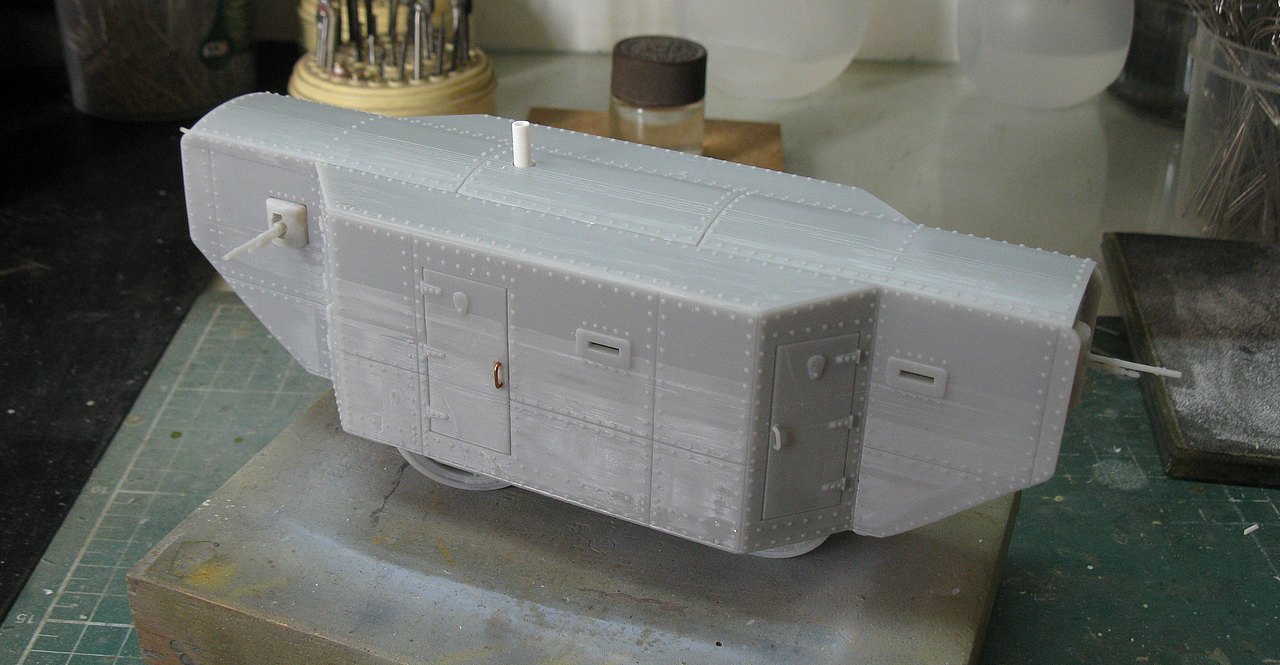
 |
The vehicle's chimney exhaust seems to me to be very skimpy and short...
I'm going to make a new one, a little bigger, with some notches
made with a scalpel on the Plastruct rod of 3,2mm in diameter, with my Dremel |
 |
| Much better... |
 |
| Testing in the vehicle... |
As I said before, ALL the machine guns came warped. I'll try to straighten these pieces with boiling water. The problem is that the plastic used by these printers is very brittle and heat resistant... Let's see what I can get...
 |
| All Hotchkiss warped... crap!! |
 |
After a nice hot bath, I managed to fix 4 of them, and one of them
was not straight at all... glad Vargas considered this hypothesis and
the kit came with an extra piece. |
 |
| Dry-run of all MGs in position... |
 |
| A real porcupine!!! |
 |
| Right side |
 |
| Rear view |
 |
| Left top view |
 |
| Left view...Notice the detail of the roller "in curve"... |
Now, it's time to painting the beast...
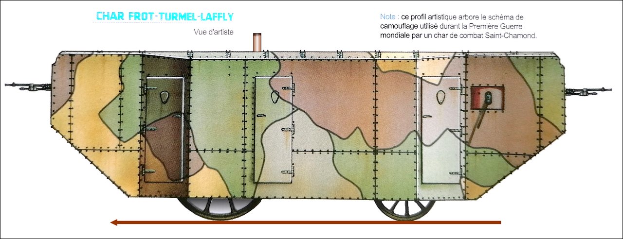
The big problem with these old vehicles and prototypes is the absence of markings...and with this, the kit gets a little "boring". As for the colors, normally the vehicles of that time used a bluish-grey, very similar to a light German-grey... But I really would like to make markings on this girl. The few surviving photos have been severely retouched, so they are unreliable. A very good friend mine (Hi, Olivier... Merci beaucoup mon ami!!) sent me images of illustrators with the vehicle sporting an operational, multicolored camouflage typical of French armored vehicles that came into operation in the WWI, but this vehicle did not go beyond the prototype stage...
 |
| Very pretty, but... |
The operational camouflage is beautiful, but historically, for a vehicle that was rejected for technical deficiencies in the tests, it bothers me...
But I remembered the canvas all painted with the manufacturer logos covering the Lincoln N° 1 Machine ( predecessor of Little Willie), when in tests...not to mention a metal plate riveted to its front hull.
 |
Lincoln Number 1 Machine with elongated Bullock type tracks and suspension The vehicle was covered in canvas (with the Foster Lincoln logo) to disguise the profile. But the presence of the turret is fully perceptible... Wellington Foundry - New Boultham, London - 19 September 1915. font: Imperial War Museum |
 |
The manufacturer metal plate in the Little Willie front hull
Bovington Museum |
Well, if there is a historical precedent, why not two??? Kojak was excited at the prospect... So, time to go out in the field, research Laffly's History.
And after many hours of browsing the most sordid and darkest corners of the Internet, I found these images, from Laffly's Commercial Sales Flyers, dating back to the early 20th century, when Laffly was known for its steam rollers, specialty trucks, and mechanical street sweepers, an incredible novelty in those times...
 |
Cover of a sales brochure showing a mechanical sweeper - 1913.
Note the company logo. |
 |
Automotive Sweeper "LAFFLY"
another cover of a sales brochure showing a mechanical sweeper - 1913
Notice the logo company |
 |
Metal plate riveted to one of LAFFLY's mechanical sweepers.
It reminds me of Little Willie's red metallic plate, seen in a photo above... |
 |
| Laffly street sweeper with water tank - 1912 |
 |
Photo of the inside of one of the 1923 sales brochures,
showing a Laffly sweeper in action, on the streets of Paris. |
But the best comes now: I discovered a Laffly logo from 1913, in which, behind the Company's letters, a steamroller manufactured by them appears, identifying the logo with the machine, in the desired period of time. BINGO!!
 |
Sales flyer for LAFFLY's steamrollers, with the machine's silhouette
visible behind the logo... more specific than that, just a picture of the Holy Grail!!!
note, out of curiosity, the number of phone numbers listed...only 4. |
 |
| Detail of the flyer, showing the silhouette and the machine!! |
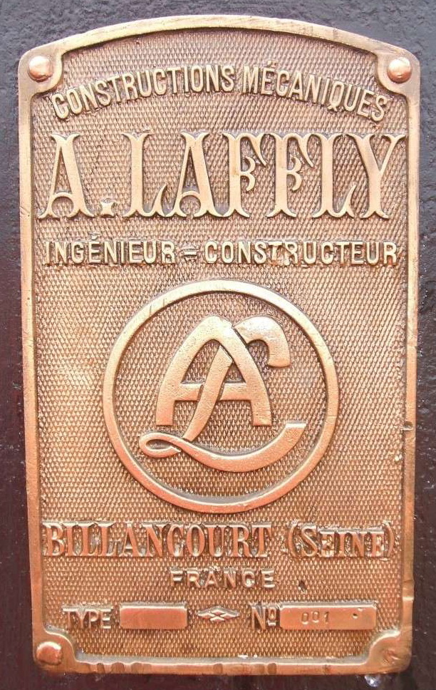
After that, I went looking on the internet for something with that logo and I found this wonder, an enameled plate from the radiator of a Laffly truck from the beginning of the century.
 |
| Enamelled radiator plate of a Laffly truck |
Now we have the brand logo and an example of an enamel plate. My idea is that THEY COULD HAVE PAINTED the logo on the side of the vehicle and COULD HAVE RIVETED a branded plate to the vehicle, like the Brits did with their Little Willie. After all, la publicité est l'âme de l'entreprise !!! (advertising is the soul of the business!!!).
 |
| art drawing of the Laffly radiator logo |
 |
| Logo graphic design |
 |
Art of the decals that will be printed in CorelDRAW:
the enameled plate (above) and the painted logo (in black, because
we are in the 10s of the 20th century),
with a beautiful art-deco frame surrounding everything... |
So the colors and markings on our Char Frot-Turnel-Laffly armored steamroller prototype COULD look like this (...and if anyone who disagrees, please show a decent photo proving otherwise!!)
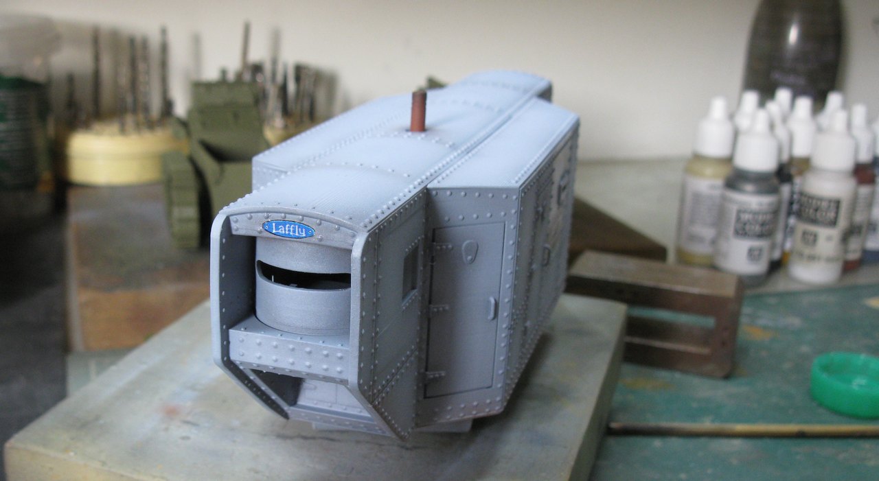
But first, primer!!!
 |
| Ops...spoiler alert!!! |
 |
Shades of bluish gray...
left view |
 |
She's so ugly, she gets to be nice...
rear left view |
 |
| rear right view |
 |
| right view |
 |
| front right view |
While the paint dries, I printed the decals, using the technique already described in the article about the
Caterpillar D7. As I mentioned above, on the sides there will be the Laffly logo "painted" on the side of the hull and on the bow and stern of this ship, the "enamelled" symbols in blue of Laffly
 |
Panzerserra Decals - The Laffly logo "painted" on the side of the hull
does not need a white background, as the decal represents
what would be a direct painting on the hull, with black paint.
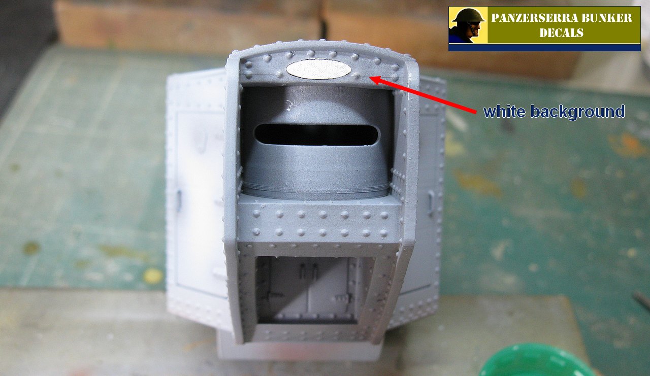
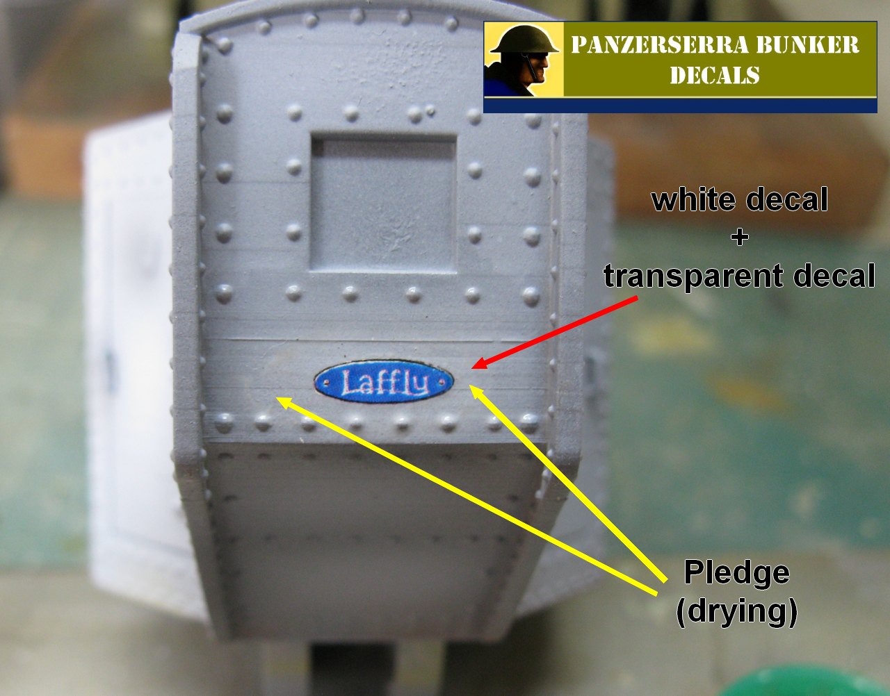
The symbols on the bow and stern of the roller need a white background,
for the blue to stand out. |
 |
Starting by the bow: white background decal,
applied in the center top |
 |
With small decals, I'm just heretical: a few drops of water + surface tension
and I have a "pot" of instant decal...
I use Pledge to pevent silvering...
In this case, I apply with a brush, along with the decal... |
 |
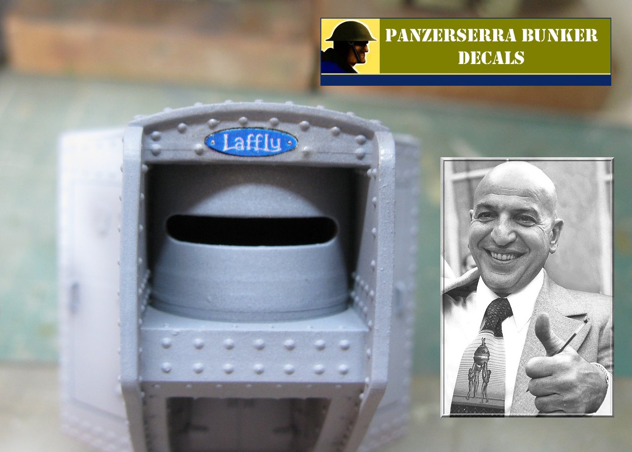
The enamel symbol...Kojak was pleased.
When the vehicle is completely finished, I will apply a drop of
transparent stained glass paint, to simulate the transparent volume of the coat of arms... |
 |
Now, let's take care of the tail: background in the roller stern...
Pledge pre-applied and drying... |
 |
| ...after the white background decal dries, I apply the colored decal, with Pledge (brush) |
 |
Now for the easiest step: the "paint" decal on the sides...
Heresy in progress: decals softening in water, with Pledge,
brush, curved scissors and tweezers |
 |
Finished painting: another excellent work from Jean-Pierre's Commercial Paintings
(a distant cousin of Kojak) |
 |
| left side. Notice the exhaust installed in the roof |
 |
| Front left view |
 |
Right view...
May the Force be with you!!!
The Char Frot-Turnel-Laffly armoured steamroller
reminds me of the Jawas Sandcrawler!!!
|
 |
| Does this remind you of anything, mon ami??? |
 |
| Rear view... Indeed, Kojak is very happy!!! |
 |
Frot-Turnel-Laffly , after the wash...
Much better!!
left view |
 |
Frot-Turnel-Laffly , after the wash...
right view |
 |
Frot-Turnel-Laffly , after the wash...
rear view |
 |
Frot-Turnel-Laffly , after the wash...
front view |
 |
No, it's not the vehicle overturning due to its poor stability...
it's the paint on the rubber treads on the tractor wheels. |
A little more weathering, but not too much... and the girl will be ready for the final step...
 |
Starting the weathering
left front view |
 |
| Right front view |
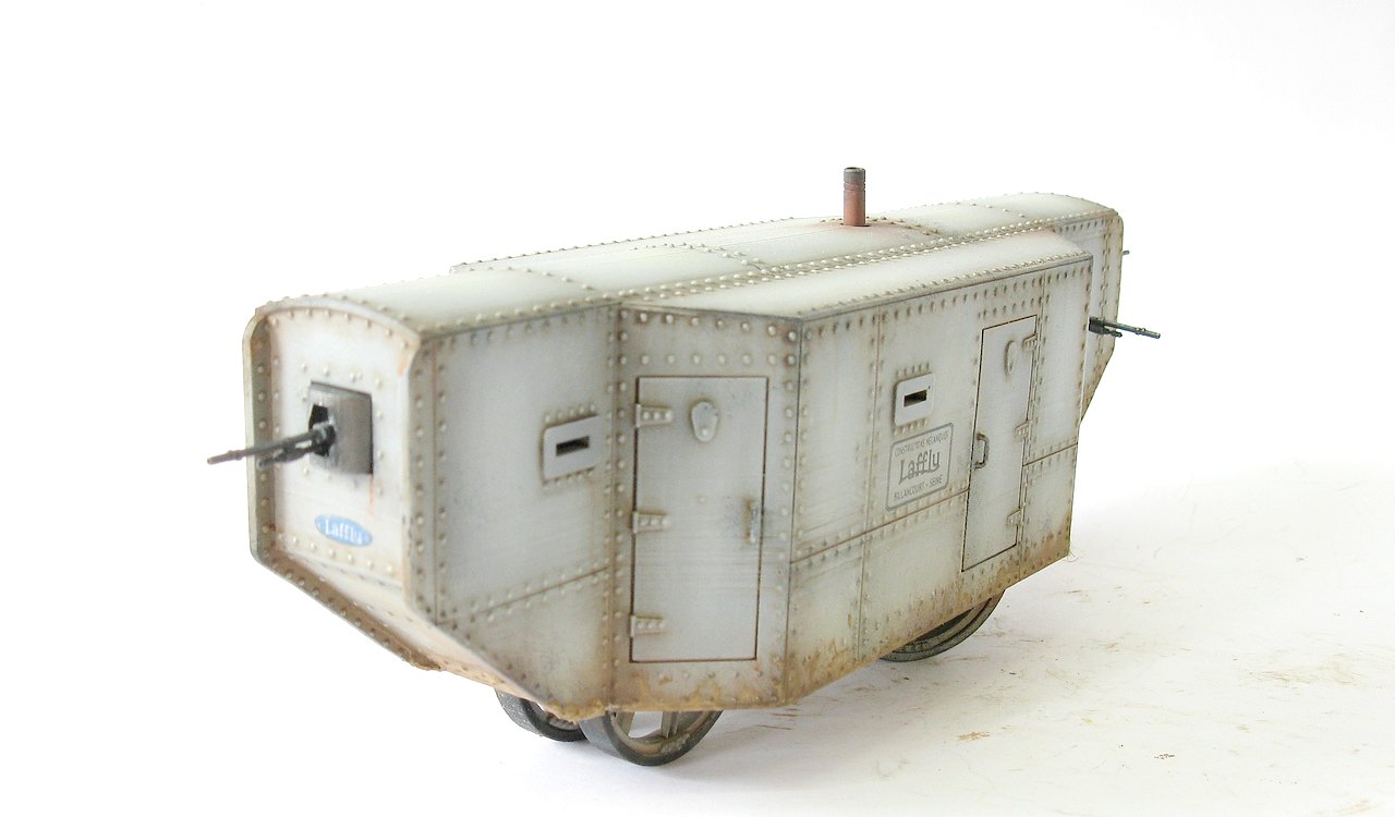
And with you, this strange and different girl, the Char Frot-Turnel-Laffly armoured steamroller prototype , performing drills in the grounds of the Corpet & Louvet factory at La Courneuve, North of Paris, France, in 28 March, 1915.
 |
Char Frot-Turnel-Laffly armoured steamroller prototype
La Courneuve - Paris, France - late March, 1915. |
 |
Char Frot-Turnel-Laffly armoured steamroller prototype
left side view |
 |
Char Frot-Turnel-Laffly armoured steamroller prototype
left rear side view
|
 |
Char Frot-Turnel-Laffly armoured steamroller prototype
right rear side view
|
 |
Char Frot-Turnel-Laffly armoured steamroller prototype
right side view
|
 |
Char Frot-Turnel-Laffly armoured steamroller prototype
right front side view
|
 |
Char Frot-Turnel-Laffly armoured steamroller prototype
left front side view
|
 |
Char Frot-Turnel-Laffly armoured steamroller prototype
left front top view
|
 |
Char Frot-Turnel-Laffly armoured steamroller prototype
with Kojak and Rover, the dog.
|
 |
From the Impossible Encounters series:
Char Frot-Turnel-Laffly armoured steamroller |
 |
The incredible evolution of French AFVs, between the first and second world wars. Char Frot-Turnel-Laffly armoured steamroller |
 |
Char Frot-Turnel-Laffly armoured steamroller prototype
La Courneuve - Paris, France - late March, 1915.
|
Merci beaucoup for following along,
my friends... See you soon!!!
À bientôt!!


Hola amigo Marcos; me parece muy triste por no decir vergonzoso que maquetas de este tipo que imagino que tendrán una tirada muy limitada para un público especial y a un precio nada económico muy seguramente, vengan con esos defectos que tu comentas y que hacen pensar que el fabricante no tiene ningún control de calidad sobre lo que saca al mercado para su posterior venta.
ResponderExcluirNo es la primera maqueta de tirada limitada que devuelvo a su fabricante por no haber pasado el más mínimo control de calidad, para mi por lo menos no vale eso de vender cualquier cosa (una pastilla de jabón) y que luego el modelista se deje los sesos y sus manos en arreglar algo que el fabricante tenía que haber entregado en perfectas condiciones dentro de la caja del kit... y más cuando hablamos de maquetas de este tipo que suelen tener un precio elevado.
Lo dicho: no todo vale en modelismo.
Un saludo.
Holla, Juan...En estos días, tenemos opciones increíbles en el mercado, pero hay espacio para empresas de letra pequeña, que se acercan a vehículos raros y diferentes. realmente, cuando compramos un kit esperamos el mejor material posible, pero las fallas ocurren. El procedimiento correcto es señalar los defectos para que se puedan hacer las correcciones. Como soy un viejo modelista, he visto muchas cosas malas y muchas cosas buenas... Lo complicado es cuando pagamos caro algo que no vale la pena, pero eso es una cuestión de necesidad personal. . Te puedo dar un ejemplo: sé que lo ideal sería construir un modelo con cañones de metal, accesorios de resina, fotograbados delicados y pistas LBL de metal... Pero el costo de tal modelo, en mi opinión, es prohibitivo. Pero para muchos modelistas esto es lo mínimo necesario... Para mi no... Lo ideal es que se pueda manejar el costo y que el kit cumpla con tus expectativas de tener un modelo raro en tu colección o por pedido de tu cliente . Estoy de acuerdo en que este modelo se puede mejorar (...y mucho...), pero llena un hueco que no existe fuera del mercado... Y cuando señalamos los defectos, el fabricante tiene una manera de mejorar su producto, en constante evolución. Mientras quiera... Pondré un ejemplo de un fabricante FANTÁSTICO, como Tamiya. Simplemente grandes modelos, pero durante cuántos años y años los modelistas no han tenido que soportar las pistas equivocadas de sus (excelentes) M4 Sherman y M3 Lee. ¿O sus ruedas de suspensión con 6 radios en lugar de los 5 correctos? Lo importante en todo esto es divertirse... Si el kit es decepcionante, quizás lo correcto sea hacer lo que hiciste: devolverlo al fabricante. Pero siempre debemos recordar que hacer un kit no es fácil... Esto no debe usarse como excusa, pero es algo que siempre debemos considerar... Pero muchas gracias por tu aportación y opinión... Esto es lo más importante de todo: intercambiar ideas y divertirnos!!! Abrazos e mucha salud!!!
ExcluirHola Marcos.
ResponderExcluirCreo sin conocerte que debemos de tener una edad muy parecida y que no
somos nuevos en esto del modelismo ninguno de los dos.
En mi colección particular de maquetas puedo decirte que siempre que
puedo evito los llamados afther markets en las maquetas que construyo
para mi, eso no quiere decir que en alguna ocasión excepcional me haya
gastado en esos accesorios más del doble del valor de la maqueta, pero
también puedo decirte que nunca he comprado ni cañones ni cadenas eslabón a eslabón de
metal, me gusta mejorar mis maquetas con elementos creados por mi
mismo, me divierte mucho más hacerlo yo que me lo ten todo hecho como a un bebé cuando le dan el biberón sus padres.
Pero eso no quita como creador de maquetas en scratch desde cero que
he sido para un fabricante de modelos en resina de mi país, que vea
ciertas maquetas de "tirada limitada" y me enfade al ver su calidad y
compararla con su excesivo precio, eso me hace daño.
Recuerdo que los originales de los vehículos militares que yo construí
para ese fabricante para el que trabajé eran perfectos, nada que ver
con las copias en resina que luego comercializaba el fabricante a precios
bastante elevados, importaba más ganar dinero que la calidad de lo
vendido... y eso no es buen negocio.
Y Tamiya... que podemos decir de Tamiya que no sepamos amigo, esa
marca FANTÁSTICA que hasta no hace tanto equipaba sus modelos con
motores para que se movieran como si de un juguete se tratara.
Tamiya es una marca de toda la vida, destaca porque sus modelos son
muy sencillos de construir casi por cualquier persona, pero su calidad en algunos detalles pues
deja mucho que desear (como cadenas u otros elementos), pero esto a
los dueños japoneses de esta marca parece no preocuparles en exceso,
de todas formas ya sabemos que la mentalidad oriental no tiene nada
que ver con la occidental... ellos son otra historia dentro de la
historia del modelismo, son como un paréntesis ( )... y les sigue
funcionando muy bien su filosofía.
Llevo unos 40 años haciendo maquetas, he construido muchísimas tanto
para mi como para coleccionistas y aficionados, he construido
originales en scratch para un fabricante de mi país y sigo haciendo
maquetas hoy en día solo para mi (menos que antes por falta de
espacio donde ponerlas), pero me sigo divirtiendo como el primer día o
más, nunca he olvidado que esto es un hobby para divertirse y pasar
momentos muy agradables.
Un abrazo y a cuidarse amigo.
Si, por supuesto!! Somos viejos modelistas, y hemos visto muchas cosas... Pero siempre lo principal: pasarlo bien sin tener que vender un riñón o una córnea!!! Un fuerte abrazo amiga!! Y sigamos nuestra lucha!!!
Excluir